
How to Pick the Right Voltage Regulator(s) for Your Design
This article demonstrates how to select the best type of voltage regulator for your particular electronics product.

Probably more than 90% of products require a voltage regulator of some kind, making them one of the most commonly used electrical components.
Unless you’re able to run everything directly off battery voltage or an external AC/DC adapter voltage, a voltage regulator is required. Odds are that multiple voltage regulators will be needed.
This article is your guide to selecting the right voltage regulator(s) for your design. We’ll cover everything from determining what type of voltage regulator you need to picking the one that meets your specific requirements.
Selecting the type of regulator you need to use
The first step in selecting the right voltage regulator is to determine your input voltage, output voltage, and maximum load current.
While many other specifications exist, these three will get you started and will help you narrow down the type of regulator you need.
Voltage regulators can be divided into two broad classifications:
- Step-down: Outputs a voltage lower than the input voltage
- Step-up: Outputs a voltage greater than the input voltage
Knowing your input and output voltages will help you to easily decide which group your regulator falls under.
Voltage regulators that require an output voltage less than the input voltage are the most common type of voltage regulator. For example, you input 5 V and it outputs 3.3 V, or you input 12 V and it outputs 5 V.
There are two types of regulators you need to consider:
- Linear regulators: Simple, cheap, and noise-free, but may have low power efficiency. Linear regulators are only capable of stepping down a voltage.
- Switching regulators: High power efficiency, but more complex and expensive, and more noise on the output. Switching regulators can be used to both step-down or step-up a voltage.
If you require an output voltage that is less than the input voltage, start by looking at a linear regulator not a switching regulator.
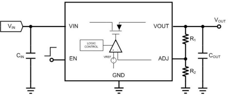
Figure 1 – A linear regulator uses a transistor and a feedback control loop to regulate the output voltage. A linear regulator can only produce an output voltage lower than the input voltage.
Linear regulators are much cheaper and simpler to use than switching regulators, therefore they should typically be your first choice.
The only times you don’t want to use a linear regulator is if the power dissipation is too high, or you need to step-up a voltage.
Determine the Power Dissipated
While linear regulators are cheap and easy to use, the major downside is that they have the potential to waste a lot of power. This can cause excessive battery drain, overheating, or damage to the product.
If you have a battery product with power being wasted as heat, the battery will drain quicker. If it’s not a battery product but still generating a significant amount of heat, this can still cause other issues with your design.
In fact, under certain conditions, a linear regulator can create so much heat that it basically destroys itself. Obviously, that’s not something you want to do.
When using a linear regulator, start by figuring out how much power is going to be dissipated by the regulator.
For linear regulators, use the equation:
Power = (Input Voltage – Output Voltage) x Current (Equation 1)
We can assume that the output current (also called load current) is approximately the same as the input current for linear regulators.
In truth, the input current is equal to the output current plus the quiescent current that the linear regulator consumes to perform the regulation function.
However, for most regulators the quiescent current is extremely small compared to the load current, so it’s sufficient to assume that the output current is equal to the input current.
As can be seen in equation 1, if you have a large voltage differential (Vin – Vout) across the regulator, and/or a high load current, then your regulator will dissipate high amounts of power.
For instance, if the input is 12 V and the output is 3.3 V, the voltage differential would be calculated as 12 V – 3.3 V = 8.7 V.
If the load current is 1 amp, then that means the regulator must dissipate 8.7 W of power. That is a huge amount of power being wasted and is more than just about any linear regulator will be able to handle.
If, on the other hand, you have a high voltage differential but you’re only running a few milliamps of load current, then the power is going to be small.
For example, in the case above if you are now only running 100 mA of load current, then the power dissipated drops down to only 0.87 W which is much more manageable for most linear regulators.
When selecting a linear regulator it’s not enough to simply ensure the input voltage, output voltage, and load current meet the regulator’s specifications.
For instance, say you have a linear regulator that is rated up to 15 V and 1 A of current. You think, “Okay, if that’s the case, I can put 12 V on the input, take 3.3 V on the output, and run it at 1 A, right?”
Wrong! You need to make sure the linear regulator can even handle that amount of power. The way to do that is to determine how much the regulator will heat up based on the power it must dissipate.
To do this, first calculate how much power is going to be dissipated by the linear regulator using Equation 1 above.
Second, look in the regulator’s datasheet under the “thermal characteristics” for a parameter called “Theta-JA” reported in units of °C/W (°C per Watt).
Theta-JA indicates the number of degrees the chip will heat up above the ambient air temperature, per each watt of power it must dissipate.
Simply multiply the calculated power dissipation by Theta-JA and that will tell you how much that linear regulator will heat up under that amount of power:
Power x Theta-JA = Temperature Above Ambient (Equation 2)
Say your regulator has a Theta-JA specification of 50°C per watt. This means if your product is dissipating:
- 1 watt, it will heat up 50°C.
- 2 watts it will heat up 100°C.
- ½ watt it will heat up 25°C.
It’s important to point out that the temperature calculated above represents the temperature differential above the ambient air temperature.
Let’s say you calculate that under your power conditions, the regulator is going to dissipate 2 watts of power. You multiply this by Theta-JA and you determine that it’s going to heat up 100°C.
Here, it’s important that you don’t forget to add the ambient air temperature. Room temperature is typically 25°C. Therefore, you should add 25°C to 100°C. Now you are up to 125°C.
125°C is the maximum temperature that most electronic components are rated for, so you never want to intentionally exceed 125°C.
You won’t typically damage your product until you get up to about 170°C to 200°C. Fortunately most regulators also have a thermal shutdown that will trigger around 150°C, so they’ll jut shut down before causing any damage.
However, some regulators don’t have a thermal shut down, so you can damage them by having them dissipate too much power.
Either way, you don’t want to design your product so that it’s constantly overheating and having to shut down to cool off.
Another thing to consider is that the air temperature might not always be 25°C.
Let’s say, your regulator still heats up 100°C when loaded, but now the ambient temperature is 50°C (such as inside a closed car on a hot summer day).
Now you’ve got 50°C plus 100°C and you’re up to 150°C when loaded. You have exceeded the specified maximum temperature and are right on the edge of triggering a thermal shutdown.
This is obviously something you want to avoid. Operating a regulator so that it regularly exceeds the 125°C specified temperature may not cause immediate damage, but it can reduce the lifetime of the component.
Low-DropOut (LDO) Regulators
In some cases, linear regulators can be extremely efficient wasting very little power. This occurs when they are operated with a very low input voltage to output voltage differential.
For example, if Vin – Vout is only 300 mV, then even with 3 A of load current the power dissipation is only 0.9 W which is low enough power to be handled by most regulators.
The minimum Vin-Vout differential that a linear regulator can operate is called the dropout voltage. If the difference between Vin and Vout falls below the dropout voltage, then the regulator is in dropout mode.
A regulator in dropout mode simply looks like a small resistor from input to output. This means the output essentially just tracks with the input supply and no regulation is actually being done.
In most cases you want to avoid operating a linear regulator in dropout mode. By no means will it damage anything but you will lose many of the benefits of having a regulator.
For instance, if you have a lot of signal noise on your input supply this will normally be filtered out by a linear regulator. However, this filtering will not occur in dropout mode, thus all input supply noise feeds straight through to the output voltage.
The reason why low-dropout regulators are so useful is they allow you to operate the regulator with very little power being dissipated. This is because a linear regulator is most efficient when the difference from Vin to Vout is small.
Many older linear regulators had very high dropout voltages. For example, the popular 7800 series of regulators have a dropout voltage specification of 2 V. This means that the input voltage must be at least 2 V higher than the output voltage.
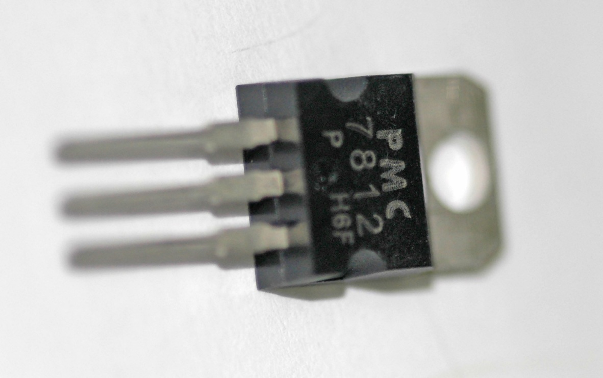
Figure 2 – Older 3-terminal linear regulators require a larger Vin-Vout voltage differential and therefore waste more power than newer LDO regulators.
While 2 V isn’t extremely high, if you’re running 1 amp of current through that regulator and you have a 2 V difference, then that’s 2 watts of power being wasted.
Newer LDO regulators may have very low dropout voltages less than 200 mV at full load.
An LDO operating with only 200 mV of voltage differential can carry 10x the current for the same power dissipation as a linear regulator operating with a 2 V differential. So 1 amp of current with a 200 mV Vin-Vout differential equates to only 0.2 W of power being dissipated.
Summary on Linear Regulators
Linear regulators are useful if:
- The input to output voltage differential is small
- You have a low load current
- You require an extremely clean output voltage
- You need to keep the design as simple and cheap as possible
As we will discuss next, switching regulators produce a lot of noise on the output and can produce a messy-looking output voltage.
That may be acceptable for some applications, but there are lots of instances where you need a very clean supply voltage. For example, when generating the supply voltage for an analog to digital converter or an audio circuit of some sort.
Therefore, not only are linear regulators easier to use, but they provide a much cleaner output voltage compared to switching regulators, with no ripple, spikes, or noise of any type.
In summary, unless the power dissipation is too high or you require a step-up regulator, a linear regulator will be your best option.
Switching Regulators
Switching regulators are much more complex to understand than linear regulators. A linear regulator is based on a power transistor which controls the amount of current allowed to feed into the output.
If the linear regulator’s control system senses the output voltage is lower than it should be, then more current is allowed to flow from input to output. And vice-versa, if the output voltage is sensed to be higher than it should be, the regulator will allow less current to flow from input to output thus acting to lower the output voltage.
On the other hand, switching regulators use inductors and capacitors to temporarily store energy before transferring it to the output.
In this tutorial I design a PCB using a simple linear regulator, and in this more in-depth course I design a custom board using a more complex switching regulator.
There are two basic types of switching regulators, step up and step down.
A step-down switching regulator is also called a buck regulator, and like a linear regulator produces an output voltage lower than the input voltage.
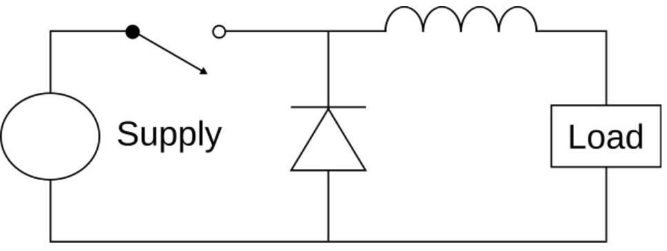
Figure 3 – A buck switching regulator uses an inductor as a temporary energy storage element to efficiently produce an output voltage lower than the input voltage.
If you started off planning to use a linear regulator (step-down) but determined the power dissipation was too high then that is when you should use a buck switching regulator.
Whereas a step-up switching regulator produces an output voltage higher than the input voltage and is called a boost regulator.
Switching regulators are highly efficient, even with very high input to output differentials.
Efficiency is equal to the output power divided by the input power. It’s a ratio of how much of the power from the input makes its way to the output.
Efficiency = Pout / Pin = (Vout x Iout) / (Vin x Iin) (Equation 3)
The efficiency equation is the same for a linear regulator. However, since the output current is equal to the input current for a linear regulator equation 3 simplifies down to simply:
Efficiency (Linear Regulator) = Vout / Vin (Equation 4)
For example, let’s say you have 24 V on the input and need to output 3 V at 1 A of load current. If this were a linear regulator, it would be functioning at extremely low efficiency and almost all the power would be dissipated as heat.
The efficiency for a linear regulator would only be 3 V / 24 V = 12.5%. This means only 12.5% of the power from the input is making it to the output. The remaining 87.5% of the power being transferred is lost as heat!
On the other hand, switching regulators commonly have power efficiencies of 90% or greater regardless of the difference between the input and output voltages. For a switching regulator around 90% of the power is being transferred to the output and only 10% is being wasted.
It’s only when Vin and Vout are close to each other that the efficiency of a linear regulator can compare to a switching regulator.
For example, if you’re input supply is 3.6 V (voltage of a lithium polymer battery) and you are outputting 3.3 V, then a linear regulator will have a power efficiency of 3.3 V / 3.6 V = 91.7%.
Step-up voltage regulators
In the majority of cases the output voltage will be lower than the input voltage. If this is the case, a linear regulator or a buck switching regulator should be used, as discussed.
However, there are other cases where you might need an output voltage higher than the input voltage. For example, if you have a 3.6 V battery and you need a 5 V supply.
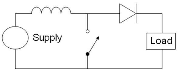
Figure 4 – A boost switching regulator uses an inductor as a temporary storage element to efficiently produce an output voltage higher than the input voltage.
Many beginners to electronics are surprised to learn that it’s possible to generate a higher voltage from a lower voltage. To perform this function a switching regulator called a boost regulator is necessary.
Unlike linear regulators, the output current for a switching regulator does not equal the input current. Instead you must look at the input power, output power and efficiency.
Let’s calculate the input current for a boost regulator. Assume the input voltage is 3 V, the output voltage is 5 V, the output current is 1 A, and the power efficiency is 90% (as specified in the datasheet).
To figure this out we need to use a little basic algebra on equation 3 to solve for the input power:
Pin = Pout / Efficiency (Equation 5)
We know the efficiency is 90% (or 0.90), and we know the output power is 5 V x 1 A = 5 W. We can calculate that the input power is 5 W / 0.9 = 5.56 W.
Since the input power is 5.56 W and the output power is 5 W that means only 0.56 W is being dissipated by the regulator.
Next, since we know that power is equal to voltage times current that means the input current equals:
Input current = 5.56 W / Vin = 5.56 W / 3V = 1.85 A (Equation 6)
For a boost regulator, the input current will always be higher than the output current. On the other hand, the input current for a buck regulator will always be less than the output current.
Buck-Boost Regulators
Let’s say you’re powering your product from two AA batteries in series. When fully charged, two AA batteries may output around 3.2 V, but when they’re close to being discharged they only output 2.4 V.
In this case, your voltage supply can range from 2.4 V to 3.2 V.
Now let’s assume you need an output voltage that’s exactly 3V regardless of the state of the batteries. When the batteries are fully charged (output of 3.2 V), you need to step down the battery voltage from 3.2 V to 3 V.
However, when the batteries are close to being discharged (output of 2.4 V), then you need to step up the battery voltage from 2.4 V to 3 V.
In this scenario, you would use what is called a buck-boost switching regulator, which is simply a combination of a step-up and step-down regulator.
You could potentially use a separate buck regulator followed by a boost regulator (or vice-versa) to solve this problem. But it is typically best to use a single buck-boost regulator.
Switching Regulator + Linear Regulators
Remember the three advantages to linear regulators: cheap, simple, and a clean output voltage.
There may be many instances where you want to use a linear regulator because you need clean output voltage, but you can’t because they waste too much power.
In this situation, you can use a switching regulator followed by a linear regulator.
Let’s say, for instance, you have an input voltage from a lithium polymer battery that’s 3.6 V, but you need a clean 5 V supply.
To do so, you would use a boost regulator to step up the voltage to a value just above your target output voltage. For example, you would use a boost regulator to step up your voltage from 3.6 V to 5.5 V.
Then, you follow that with a linear regulator that takes the 5.5 V and steps it down to 5V while also cleaning up the noise and ripple to produce a clean signal.
This is a very common technique to obtain the efficiency of a switching regulator and the noise-free output voltage of a linear regulator.
If you decide on this option and are specifically trying to filter out switching noise, be sure to note the Power Supply Rejection Ratio (PSRR) of the linear regulator.
The PSSR of a given linear regulator varies over frequency. Therefore, the PSSR is typically presented as a graph that depicts how the linear regulator rejects any ripple on its input supply over varying frequencies.
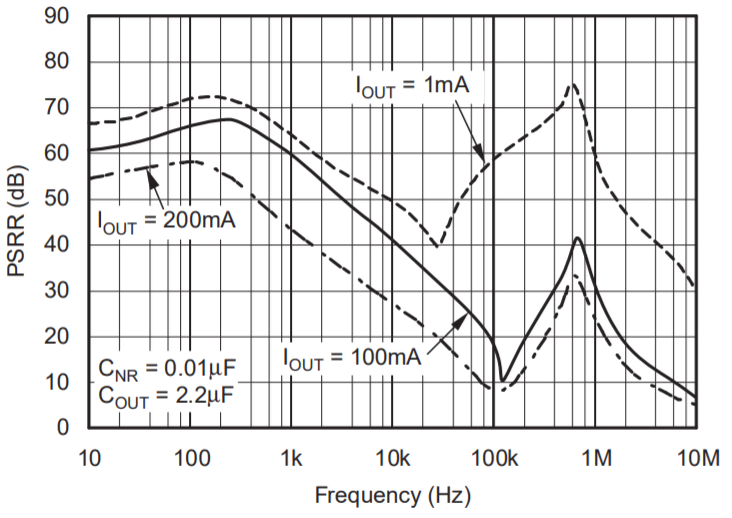
Figure 5 – Power Supply Rejection Ratio (PSRR) versus frequency for the TPS799 from Texas Instruments.
To use this graph, look at the switching frequency of your switching regulator (or of any other noise sources in your circuit). Then, look at the PSSR of the linear regulator at that particular frequency.
You can then calculate how much of the noise from the switching regulator will be removed by the linear regulator.
Summary
To select a voltage regulator for your system, start by assuming a linear regulator can be used if the input voltage is higher than the output.
Only if that wastes too much power, then use a buck switching regulator.
If you need an output voltage higher than the input, then use a boost switching regulator.
If you have a situation where the input voltage can be higher or lower than the output voltage, then you want a buck-boost switching regulator.
Finally, if you need a clean output, but need the power efficiency of a switching regulator, then use a switching regulator followed by a linear regulator to clean up the supply voltage.
Other content you may like:
- Linear and Switching Voltage Regulators: An Introduction
- Introduction to Switch Mode Power Supply Design
- Introduction to Battery Chargers
- How to Switch Large Loads with a Microcontroller Using Transistors
- Charging Methods for Lithium-Ion Batteries

Thank you John, this article was fantastic! 🙂
I am tying convert a fluctuating voltage input of 20-30vdc to a ‘clean’ 12vdc output to operate a relay.
Would a simple linear regulator work in this instance? or do I need to use a low dropout regulator? Or is the difference too great that I actually need a small transformer?
Thank you.
Thank you Joe!
You can maybe use a linear regulator but it depends on the current and you have to be careful that you don’t dissipate too much power otherwise the regulator will heat up and shut off. The power dissipated is equal to (Vin-Vout)*Iout.
What you may need is called a buck switching regulator. Whenever you need to step a high voltage down significantly that has high current then you need to use a buck because they are much more efficient and don’t dissipate much power so excessive heat isn’t usually as much of an issue.
Thank you for sharing such a useful article with us.
Thank you for explaining how selecting a voltage regulator for your system depends on whether the input voltage is higher than the output. I imagine the quality of the voltage regulator also plays a key role in the power efficiency and that it would be wise to consult a professional on what would be best to use for your system. I’m looking into shunt regulators for high voltage, and I’m wondering if they’ll also be available at the same places as linear and switch voltage regulators.
thank you for this useful article.
Good read! useful content.