
Introduction to Programming STM32 ARM Cortex-M 32-bit Microcontrollers (Updated 2022)
In this in-depth article you will learn how to develop embedded firmware for STM32 Cortex-M 32-bit microcontrollers using the various development tools.
The STM32 series are some of the most popular microcontrollers used in a wide variety of products.
They also have an excellent support base from multiple microcontroller development forums.
This family of microcontrollers from STMicroelectronics is based on the ARM Cortex-M 32-bit processor core.
STM32 microcontrollers offer a large number of serial and parallel communication peripherals which can be interfaced with all kinds of electronic components including sensors, displays, cameras, motors, etc. All STM32 variants come with internal Flash memory and RAM.
The range of performance available with the STM32 is quite expansive.
Some of the most basic variants include the STM32F0 and STM32F1 sub-series that start with a clock frequency of only 24 MHz, and are available in packages with as few as 16 pins.
At the other performance extreme, the STM32H7 operates at up to 400 MHz, and is available in packages with as many as 240 pins.
The more advanced models are available with Floating Point Units (FPU) for applications with serious numerical processing requirements.
These more advanced models blur the line between a microcontroller and a microprocessor. Some models of the more advanced processors like the H7 series even offer dual-core CPUs in a microcontroller!
Finally, the STM32L sub-series is designed specifically for low-power portable applications running from a small battery.
Development Tools
There are several software development tools available for code development on STM32 microcontrollers.
The software tools are available as Integrated Development Environments (IDE) which combines all of the necessary tools into an integrated environment.
Two common development packages include:
- Keil MDK ARM (uVison5 IDE) – The MDK ARM IDE is a very stable development environment which can be downloaded for free. It allows development of code up to a program size of 32 KB. For developing larger programs a licensed version needs to be purchased here.
- STM32CubeIDE – Recommended for new STM32-only toolchains, this IDE straight from ST integrates their STM32CubeMX tool into a full-fledged Eclipse-based IDE. It can be downloaded for free here
There are also several other IDEs that are available for use with STM32 microcontrollers.
However, this article focuses on developing and flashing a program using the very popular Keil MDK ARM uVision5 IDE.
Apart from the software tools, an In-Circuit Serial Programmer (ICSP) is required to program and test the code on the actual microcontroller.
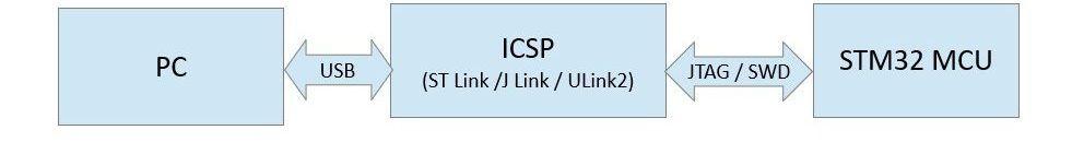
Programming the STM32 via the In-Circuit-Serial-Programmer (ICSP)
The ICSP is required to interface the microcontroller to the PC software tools via a USB port.
The ARM Cortex-M microcontrollers support two programming protocols: JTAG (named by the electronics industry association the Joint Test Action Group) and Serial Wire Debug (SWD).
There are several ICSP programmers available that support these protocols, including:
- Keil U-Link 2
- Segger J-Link
- ST-Link
Developing the First Application
It’s always easiest to start with a readily available basic code framework. Then, add the code that is required for the specific application and model of microcontroller.
Fortunately, STMicroelectronics provides a very useful graphical tool called STM32CubeMx that helps in creating a basic application project for any STM32 microcontroller of your choice by auto-generating hardware initialization code.
It also can be used to configure the peripherals on the multiplexed pins of the microcontroller, automating tasks such as detecting when a peripheral will no longer work because another peripheral is already using the pins it has access to.
The STM32CubeMX tool can be downloaded from here.
The STM32Cube suite comes with an extensive set of drivers for all types of peripherals and support for an optional FreeRTOS (a free Real-Time Operating System) pre-integrated with the code, as well as other middleware like the FAT file system and USB.
The following section describes in detail how to create a simple UART application for the STM32F103C8T6 microcontroller that echoes whatever is typed on a terminal window.
- Install the STM32CubeMX software.
- Run the application and select New Project. It will then open the MCU Selector window as shown below.
- Double click to select the microcontroller model being used. In this case we’re using the STM32F103C8T6. It then takes you to the pinout page for the selected microcontroller.
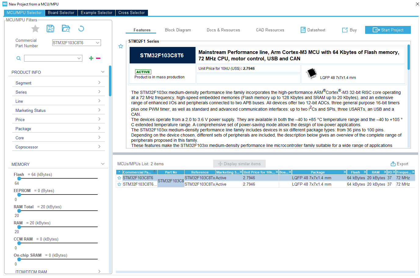
The STM32F103C8T6 is an ARM Cortex-M3 core with 64KB of Flash memory and 20KB of RAM memory.
Notice that when you select a microcontroller from the menu, a section with a detailed overview of the chip appears, as well as useful items like CAD resources and all of its documentation.
You can download ECAD symbols/footprints for the part and any other needed materials right from this window, which is a huge time-saver.
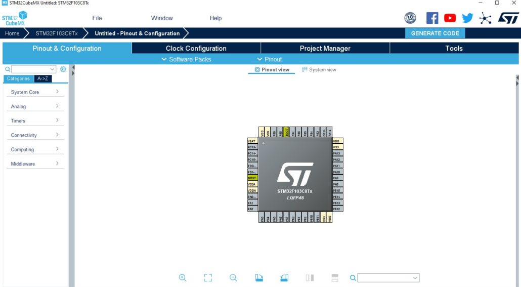
Double-clicking on the part in the list on the bottom right will initialize the project, showing the following window:
The tab that initially opens up, Pinout & Configuration, is the primary interface for the MCU. This is where peripherals are enabled and configured, and pin usage is labeled on the Pinout view in the center.
Peripherals, middleware, etc. can all be configured using the drop-down menus on the left sidebar.
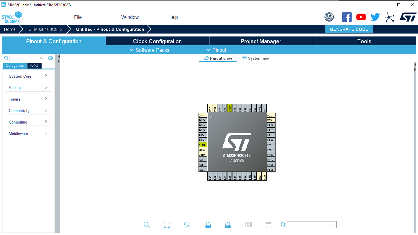
Since this example uses UART, we go to the Connectivity option in the left sidebar, select USART1 peripheral, and enable it in Asynchronous mode.
STM32CubeMX automatically initializes the configuration and assigns the pins:
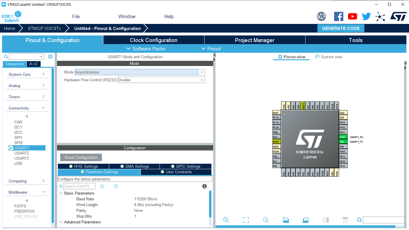
Notice that PA9 and PA10 are labeled with their new assignment. Additionally, there is a Configuration menu for UART available where settings can be tweaked.
We will be using the default settings, noting that the baud rate is at 115200 for later communication with the MCU.
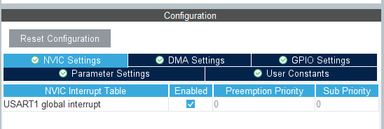
Since the example will require interrupts enabled for UART, go to NVIC Settings and check Enabled next to USART1 global interrupt.
Now we are ready to generate the project code.
STM32CubeMX allows code generation for various types of project structures, which is a large part of its appeal – it can be used to generate projects for EWARM, MDK-ARM (what we will be using), or a barebones Makefile project.
Navigate to Project Manager–>Project in order to add the new project name and select the tool chain IDE to be used.
For this example, set the project name to ‘UARTEcho’ and select the MDK-ARM IDE for the project development.
Finally, generate the project code by clicking Generate Code in the upper right.
Building and Flashing the Code
Now, open the generated MDK-ARM project file UARTEcho\MDK-ARM\UartEcho.uprojx.
If this is your first time using this MCU, then you may have to install the Keil-MDK5 pack for it in the IDE prior to opening the project.
This program so far just initializes the UART peripheral and stops in an infinite loop.
It’s important to note that the STM32Cube generates /* USER CODE BEGIN x */ and /* USER CODE END x */ comment blocks to implement the user specific code.
The user code must be written within these comment blocks.
Whenever the code is re-generated with modified configurations the STMCube tool retains the user code within these user comment blocks.
Next, define a global variable to receive a byte from the UART in the main.c source file:
/* Private variables ---------------------------------------------------------*/
static uint8_t recv_data;
/* USER CODE END PV */
After all of the initialization code, enable the driver to receive 1 byte.
The following function enables the RXNE interrupt bit.
HAL_UART_Receive_IT(&huart1, &recv_data, 1);
/* USER CODE END 2 */
Now, add a callback function to handle the receive interrupt and transmit the received byte.
void HAL_UART_RxCpltCallback(UART_HandleTypeDef *huart)
{
HAL_UART_Transmit(huart, &recv_data, 1, 1000);
}
/* USER CODE END 0 */
Finally, we need to compile the code and flash (download) it to the microcontroller.
When the Keil MDK ARM IDE is installed, drivers for ST-LINK V2, J-Link and Ulink2 are available.
The ST-Link debugger will be selected by default.
Go to Projects–>Options for Target and in the Debug tab select the ICSP programmer used.
Flash the code by selecting Flash->Download.
The microcontroller will now echo any data received over the UART. It can be connected to a PC by using a USB-to-Serial Converter.
On the PC open the COM port with a terminal application using the settings of 115200-8-N-1. Now, anything that is sent from the terminal will echo back through the microcontroller.
Interrupt System
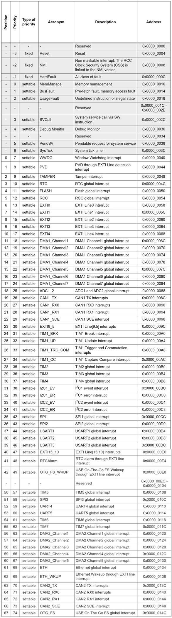
The STM32 interrupt system is based on the ARM Cortex M core NVIC peripheral.
The STM32 MCUs support multiple maskable interrupt channels apart from the 16 interrupt channels of the ARM core. For example, the STM32F1 MCU series supports 32 maskable interrupts.
Extended Interrupts and Events Controller (EXTI)
The STM32 MCUs have an extended interrupts and events controller which manages the external and internal asynchronous events/interrupts and generates the event request to the CPU/Interrupt Controller and a wake-up request to the Power Manager.
Each of the one or more EXTI lines are mapped to one of the NVIC interrupt vectors.
For the external interrupt lines, to generate an interrupt, the interrupt line should be configured and enabled.
This is done by programming the two trigger registers with the desired edge detection and by enabling the interrupt request by writing a ‘1’ to the corresponding bit in the interrupt mask register.
External Interrupt and GPIO mapping
Each of the GPIO available on the system can be configured to generate an interrupt. But each of the EXTI interrupt lines is mapped to multiple GPIO pins.
For example, PIO0 on all the available GPIO ports (A,B,C, etc.) will be mapped to the EXTI0 line. PIO1 for all ports will be mapped to the EXTI1 line and so on.
Some of the EXTI lines are combined to a single NVIC vector. For example, EXTI4_15 is mapped to a single vector address so there will be a single interrupt routine for all the interrupts from PIO4 to PIO15.
But the source of the interrupt can be identified by reading the interrupt pending register.
One important thing to consider while designing a system using the STM32 MCUs is the selection of the GPIO pins for the interrupts.
The MCU may have more than 16 GPIOs available on the device but there are only 16 external interrupt lines available.
For instance, the EXTI_0 can be mapped to either PA0 or PB0 but not both.
Choose pins for the external interrupts that can be uniquely mapped to one of the EXTI lines.
Recall that when setting up the UART peripheral initially we enabled the USART1_IQRn interrupt by checking Enable in the NVIC Settings under the Configuration section for USART1.
The code to enable the interrupt for the module will be generated in the stm32f1xx_hal_msp.c in the HAL_<module>_MSPInit(…) function.
HAL_NVIC_SetPriority(USART1_IRQn, 0, 0);
HAL_NVIC_EnableIRQ(USART1_IRQn);
The code generated by the STM32 Cube will have the IRQ_Handler implementation of all the interrupts. When the interrupt is enabled the code will be included into the application.
Usually, the generated code already handles the IRQ and clears the flag which generated the interrupt.
It then calls an application callback that corresponds to the event that generated the interrupt for the module.
The STM32 HAL (Hardware Abstraction Layer) implements a callback for each of the event types within each module as part of the driver.
Directly, when an interrupt is triggered for an enabled IRQ, a function with the format <peripheral>_IRQHandler() is called, which can be seen in stm32f1xx.it.c:
* @brief This function handles USART1 global interrupt.
*/
void USART1_IRQHandler(void)
{
/* USER CODE BEGIN USART1_IRQn 0 */
/* USER CODE END USART1_IRQn 0 */
HAL_UART_IRQHandler(&huart1);
/* USER CODE BEGIN USART1_IRQn 1 */
/* USER CODE END USART1_IRQn 1 */
}
The HAL_UART_IRQHandler() function is a HAL-specific function that does some cleanup around the interrupt like clearing the flag that triggered it and calling some callback functions depending on the type of interrupt.
In this example the Rx Transfer Complete callback was copied from the stm32f1xx_hal_UART.c file.
The callback functions within the driver will be implemented with a __weak linker attribute.
The user needs to implement a copy of the necessary callback function by removing the __weak attribute in one of the application files and then writing the specific handling required within that function.
* @brief Rx Transfer completed callback.
* @param huart UART handle.
* @retval None
*/
__weak void HAL_UART_RxCpltCallback(UART_HandleTypeDef *huart)
{
/* Prevent unused argument(s) compilation warning */
UNUSED(huart);
/* NOTE : This function should not be modified, when the callback is needed,
the HAL_UART_RxCpltCallback can be implemented in the user file.
*/
}
Conclusion
This tutorial is an introduction to writing an application that works with the STM32 family of microcontrollers.
There are several other methods for writing an application but the STM32Cube discussed is an easy and intuitive method to get started.
This tool simplifies the initialization of the microcontroller peripherals. It also improves the maintainability of the code especially when there are hardware revisions which require remapping of the signals to different pins.
Another advantage of using the STM32CubeMX tool is that it generates a report of the user configuration for the microcontroller.
In this report it details the clock tree, pin mapping and hardware module configuration which are all very useful.
There are also several other code libraries and example programs available for all the STM32 variants. Support for several IDEs is also included.
If your project requires a sophisticated 32-bit microcontroller then I highly recommend the STM32 series. Not only are they powerful and popular, but STM32 microcontrollers are also quite affordable.
Other content you may like:
- Auto-Generated Firmware Code: Deconstructing an STM32CubeMX Project
- Introduction to the STM32CubeIDE for STM32 Microcontrollers
- Introduction to Embedded Firmware Development
- How to Select the Microcontroller for Your New Product
- Introduction to the Ultra High-Performance STM32H7 32-bit Microcontroller

Hi Jhon,
Your post on Predictable design is really brilliant, although most of us here are from technical experience, Your post is an eye opener for anyone who has an startup idea.
Its Really useful for novice user. I am so thankful for this user guide, it helped me a lot to initiate the programming.
STM32CubeMX generates nonfunctional timer interrupt code for the common STM32F103 MCUs (as of 2021-01-14). I have tried a handful of published simple instructional timer interrupt-driven examples – none of them work because the function HAL_TIM_PeriodElapsedCallback() is neither defined nor called in the generated project code.
i want to program stm32 controller over wifi, Is it possible to program ?if possible then how can i do that with stm32f1?
Hi, is the J-tag required for this process?
So, I bought an stm32 microchip and made somewhat of a breakout board for it (all the pins of the chip are connected to holes on the board).
Is it possible to program with only the ICSP and not the JTAG.
I ask this because i want to program only the microchip and I do not have a development board.
Do i need to get the JTAG seperately.
Thanks
hi John, some how I ran across you via a telegram talking about programing STM32 controllers. This group is into Bitcoin mining. Most of the miners are rendered not profitable in a very short time frame. I have 4 of these now. One could be profitable if reprogrammed to turn up the hash rates and stabilize them. It is normal for some to come into mining at twice the target rate. I would imagine this drop happens after it reads the program in the STM32 controller that controls the hash rates on the hash cards. I can see big money bringing lots of miners back to work.
Thanks for the comment Bruce!
Hey John, Coocox is dead. It has no support of any kind, the web and the forums are down.
Also the Keil compiler has no size limitations for cortex M0:
http://www2.keil.com/stmicroelectronics-stm32/mdk
The Atollic Trustudio is also free and a good tool:
https://atollic.com/
Thank you Abel, looks like I need to make a few updates. I will do this asap.
John
Hi John. Thank you for the informative article. Unfortunately, one of your links is out of date. I think that it was out of date in 2016. Here is an explanation, and I just clicked this right now.
https://www.cnx-software.com/2018/07/25/coocox-coide-and-gcc-toolchain-download/
Thank you Eric for bringing this to my attention! I have updated the link to the link you provided.
John
Hi Mohan and John,
Excellent point raised about only 16 external interrupts being available, which means that if for example you used it on PA0, then you can’t use it on PB0 as well… that burnt us before, because we did not RTFM 🙂
My go-to tools are Segger J-Link, Makefile for building and Segger Ozone debugger. Attolic TrueStudio looks like a better alternative to CoIDE now that ST have acquired them.
IMO the STCube libraries are pretty obfuscated, but good enough for quick proof-of-concept. There are a lot of good libraries out there and I’m creating one too with portable architecture support for AVR and STM32L0 (it’s a WIP):
https://github.com/piconomix/piconomix-fwlib
Regards,
Pieter
Thanks Pieter for the comment!
Could you please using OLD stm32f4Discovery board show step by step some USB devices – mouse, keyboard, serial port, flash drive-input via a user button. I mean not just a code by exact step by step.
Thank you.