
Electronic Lab Setup: Tools and Equipment Requirements
If you are a maker or engineer planning to develop your own electronic product, then you’re going to need a way to test, program, and debug the electronics. In this article I will discuss how you can construct your very own lab setup for testing out all your product concepts.

The Basics – Hand Tools
Regardless of what kind of electronics lab is being set up, and what range of products will be tested and analyzed, some basic hand tools will always be required.
These need not be sophisticated. A few inexpensive tools are typically needed, as shown in figure 1 below:
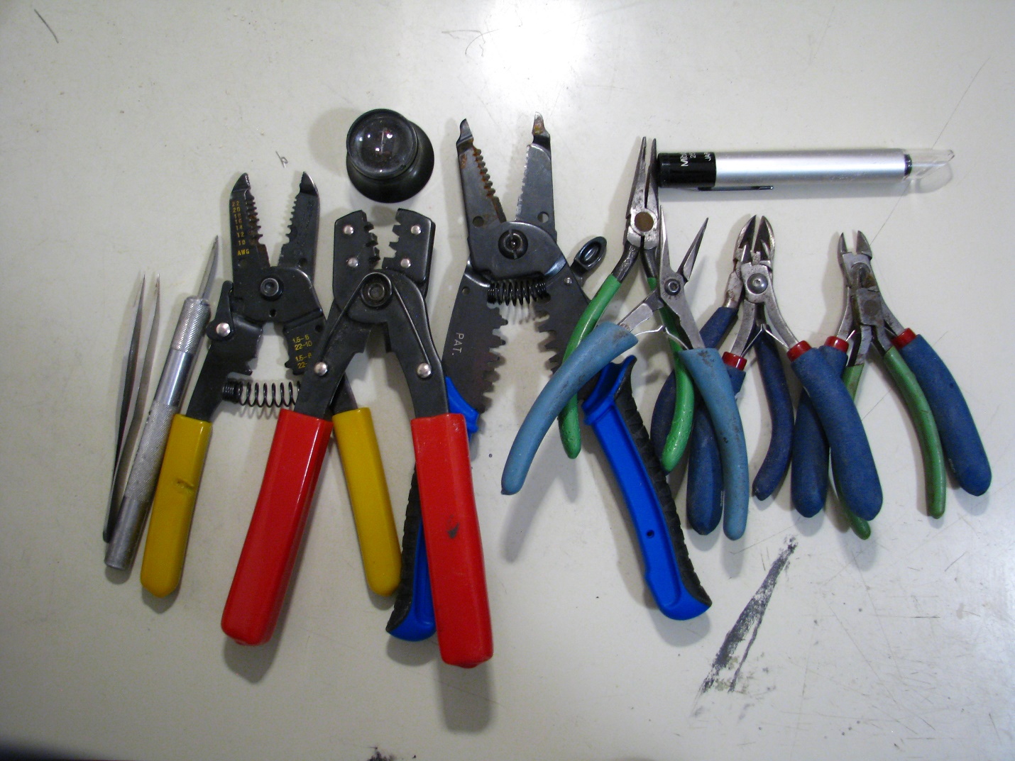
Figure 1 – Basic hand tools
While the tools will vary from one setting to another, it is safe to say that, at the very least, a decent lab setup should have: wire cutters and strippers; pliers -both regular and long nose; and tweezers.
Because, these are relatively inexpensive tools, I highly recommended you choose high quality tools over more flimsy ones.
The Basics – Prototyping
Next to the hand tools are the basic requirements for doing prototyping. Here again, some tools and basic supplies should be part of any lab.
Since prototyping requires actually building stuff, here are some basic tools, and their roles in the prototyping process.
The first obvious one is a good soldering iron, as shown in figure 2. It is well worth it to invest in a temperature-controlled, high quality soldering iron, with easily interchangeable soldering bits.
The choice of soldering bits will depend on the type of soldering that is being carried out. Some soldering irons are fairly high powered, and can be accurately temperature-controlled to accommodate both very delicate precision soldering jobs and jobs requiring high power.
An example is the process of soldering large components connected to large ground planes that will, in essence, act as a heatsink that quickly cools the soldered point so that the solder will no longer melt properly.
As shown in the picture, the use of two soldering irons, each with different power ratings, should be considered.
For small precision jobs a soldering iron of 25 – 35 W is typically used and larger jobs need somewhere in the range of 60W to 100W.
Along with the soldering iron, is the choice of the actual solder type and its diameter. Here again, it is a good idea to have at least two, if not more, diameters.
It is close to impossible to solder closely-spaced component pins with a large diameter solder, and, conversely, it is quite hard to use very thin solder to try to solder a power resistor, for example.
The amount of solder needed for such a job might require feeding a lot of solder to completely cover the solder joint area. Using a thin solder might actually result in overheating the component due to the longer time needed to feed enough of a small diameter solder to completely wet the whole solder area.
For the actual solder, a flux-core solder is recommended. For prototyping purposes, leaded or lead-free solder can be used. In general, leaded solder tends to be a bit easier to work with because it usually melts at lower temperatures. But lead is also toxic so always be sure to use proper ventilation when soldering.
Other essential supplies for soldering are a wet sponge, or cleaning wool, to clean the soldering iron tip. It is a good idea to always clean the tip before each use.
You will also need solder wick, in many sizes if possible, and a tip tinning paste. This helps to keep the tip properly tinned, and make it wet more easily.
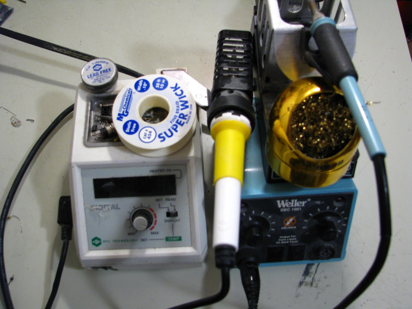
Figure 2- Soldering irons and supplies
To connect the components together to get to an actual prototype, you have several options. If the design is not a high frequency or a high clock-rate design, then prototyping using breadboards and stripboards can be considered. Some examples are shown in figure 3.
In addition, it might also be a good idea to have a collection of SMT to through-hole adapter boards (figure 4). Of course, if the design contains high frequency circuitry, then prototyping should be done using actual PCBs.
There are several Chinese PCB manufacturers (Seeed Studio, PCBWay, Bittele) that offer reasonably-priced PCB services with reasonable turn-around times.
In general, anything that has frequency components above fifty MHz should be prototyped using actual PCBs. In these cases, the prototype PCBs can have many test points that can be accessed for probing critical points of the design. These can, of course, be removed in the final version.
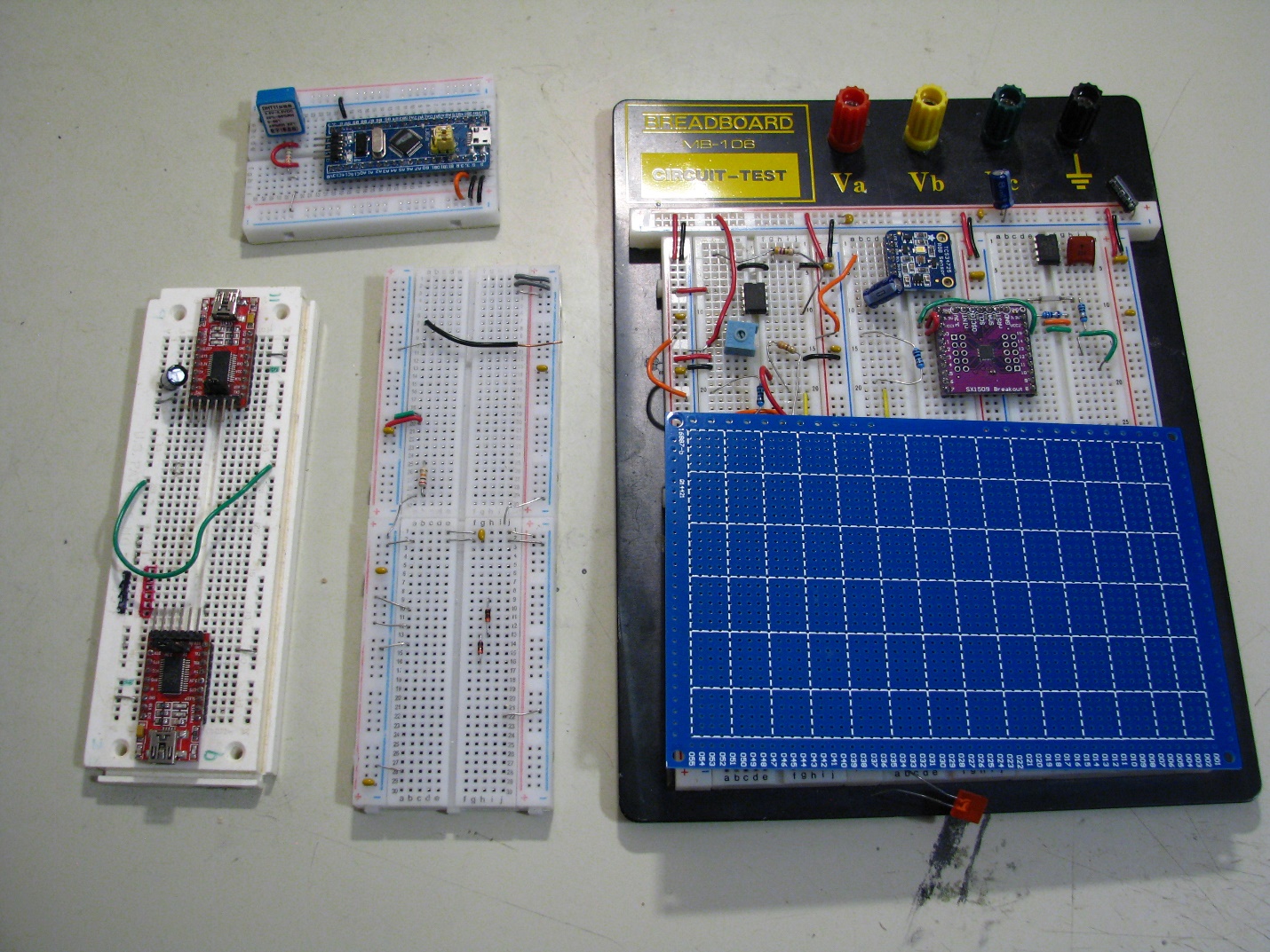
Figure 3 – Examples of breadboards and stripboard
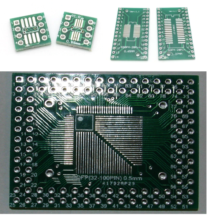
Figure 4 – SMT to through-hole adapter boards
Finally, most prototypes will require rework and fly-wiring as part of the debugging process. You will need a collection of small hand drills, with interchangeable drill bits and cutting blade attachments.
Additionally, when de-soldering small SMT components I recommend using a small, hot-air rework station. At the very least, a hot-air gun with multiple interchangeable nozzle types should be used.
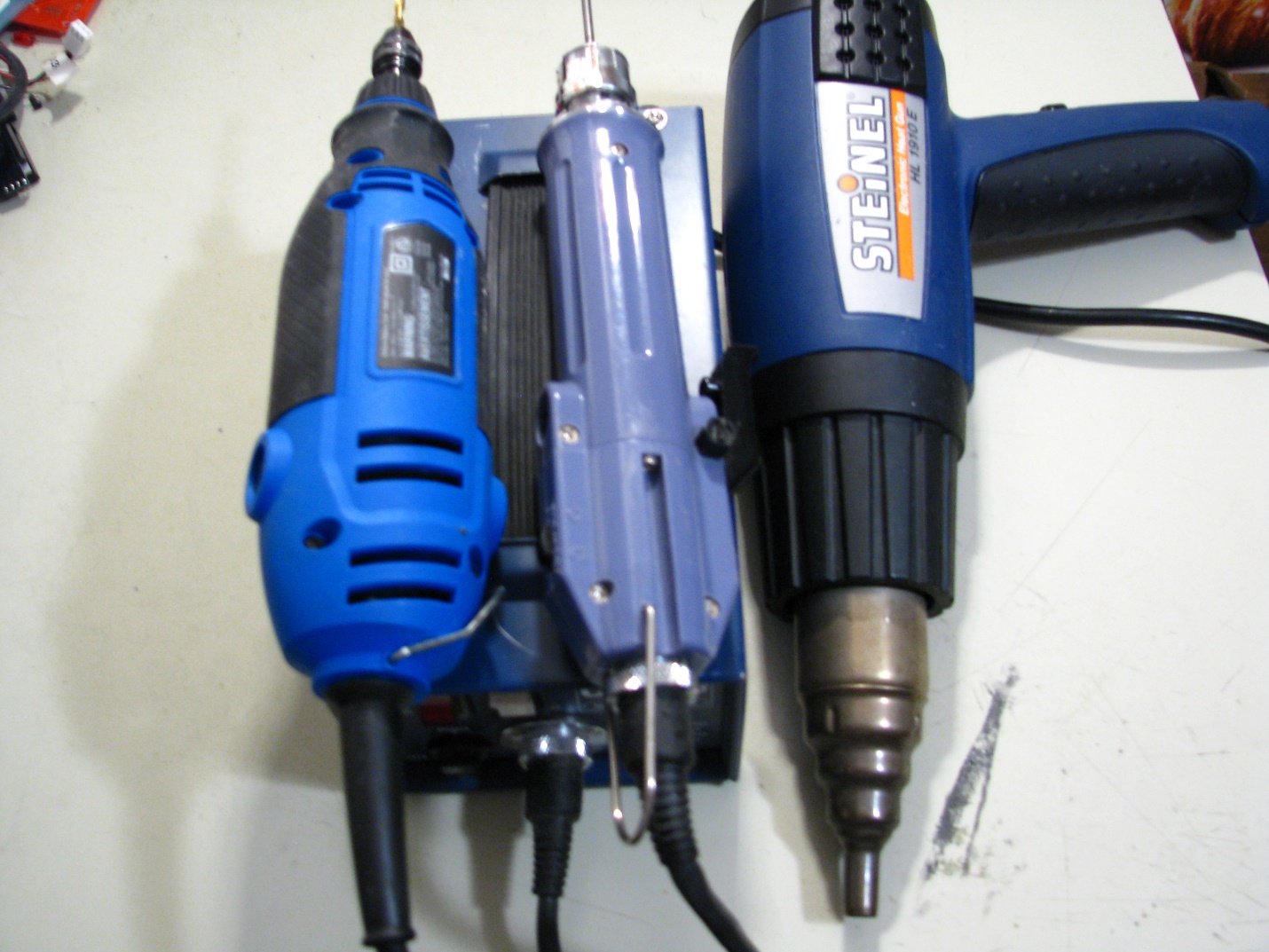
Figure 5 – Small powered hand tools for prototype rework
Instruments for debugging and testing
After building your prototype, you will need to test and debug it. The first thing you want to do is to actually power-up the prototype. You will need one or more power supplies.
At the very least, one lab-grade power is recommend for initial bring-up of a prototype when the power-on behavior of the design is completely unknown.
In such cases, it is a good idea to, at least, limit the current from the power supply to prevent catastrophic damage to the prototype. Figure 6 shows examples of lab-grade DC power supplies.
Another good feature that most lab-grade DC supplies have is local sensing, also known as Kelvin sensing. This makes sure that the voltage delivered at the load is precisely what it was set to at the power supply end by compensating for the voltage drop in the power delivery cable due to the current flowing through it.
Note that some of the more expensive DC power supplies, like the one in Figure 6, can source and sink current, and can also be remotely accessed. Thus, they can be made part of automated test setups controlled by a Python script or LabView.
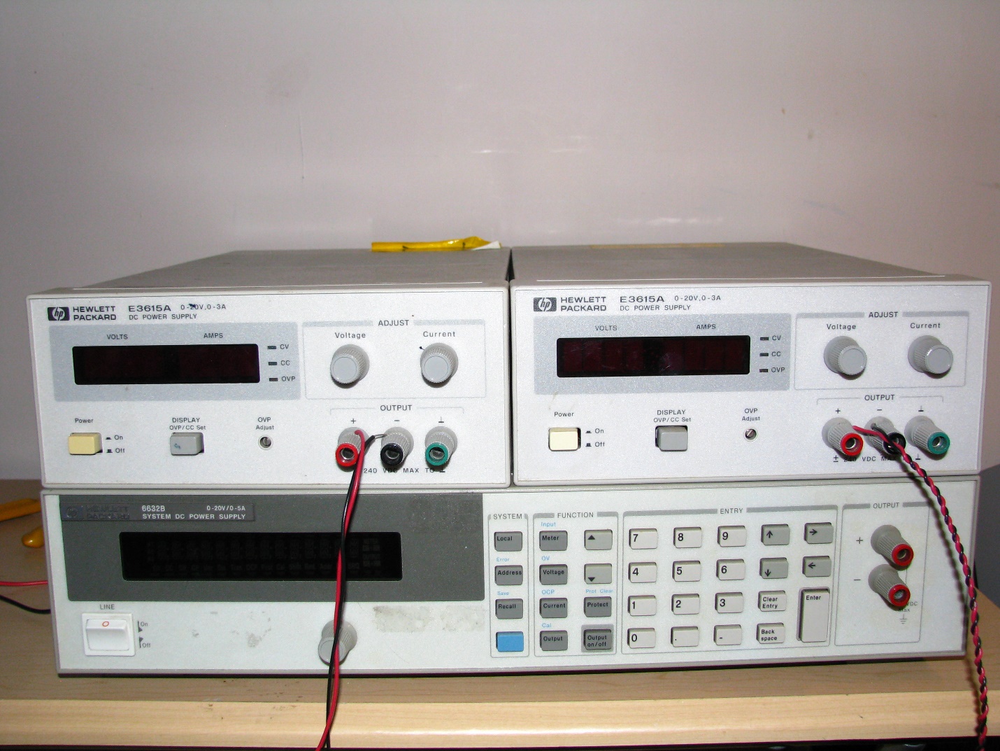
Figure 6 – Lab power supplies
Another basic instrument that should be part of any electronic lab is a multimeter. Digital multimeters, or DMMs, are fairly inexpensive, and every lab should have at least one, if not more.
Figure 7 shows a few examples of DMM’s. They basically come in two varieties: handheld and benchtop. These differ in cost, features and capabilities.
For example, the benchtop type has much better resolution. It can also more accurately measure resistance using a four-wire technique that compensates for the resistance of the measuring probe.
Also, most handheld DMMs have very poor acquisition rates. For example, when measuring a current that has regular short bursts, the reading can be quite off due to the multimeter simply missing the current bursts.
Measuring voltages with high crest factors is another area where handheld DMMs might produce very grossly inaccurate readings. Benchtop DMMs are much better in that respect, since their ADC techniques used to acquire the input signal in each case are quite different.
Finally, most benchtops can be remotely accessed, and can be made part of automatic setups, again using Python, LabView or something similar.
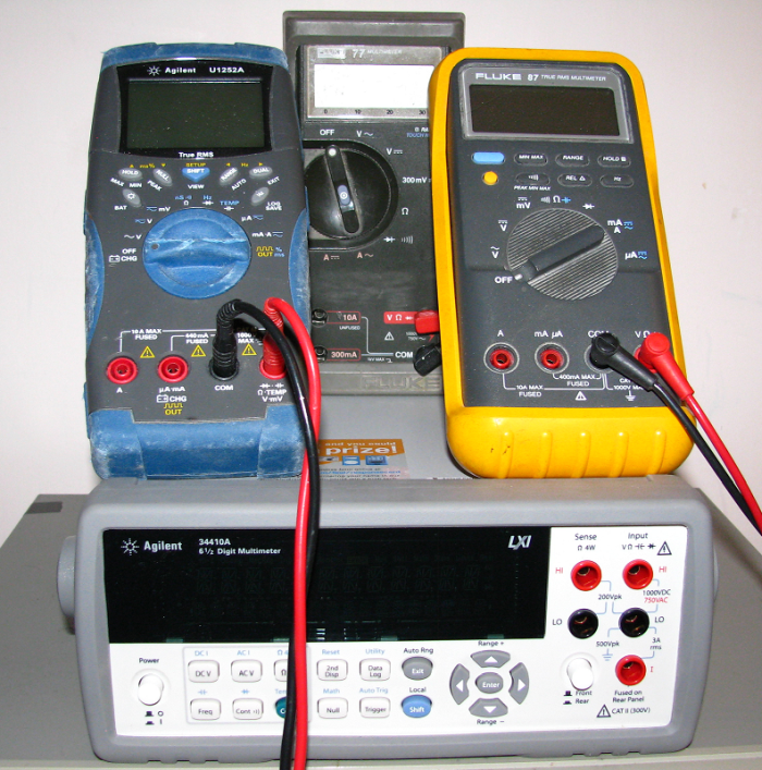
Figure 7 – Typical digital multimeters
Finally, to complete your basic lab setup, you will need an oscilloscope. The best way to analyze how a design is behaving is to probe the proper points, and observe the actual signals.
Scopes tend to be a big investment for a small lab. However, even an old or second-hand analog scope, like the one in figure 8, is better than nothing.
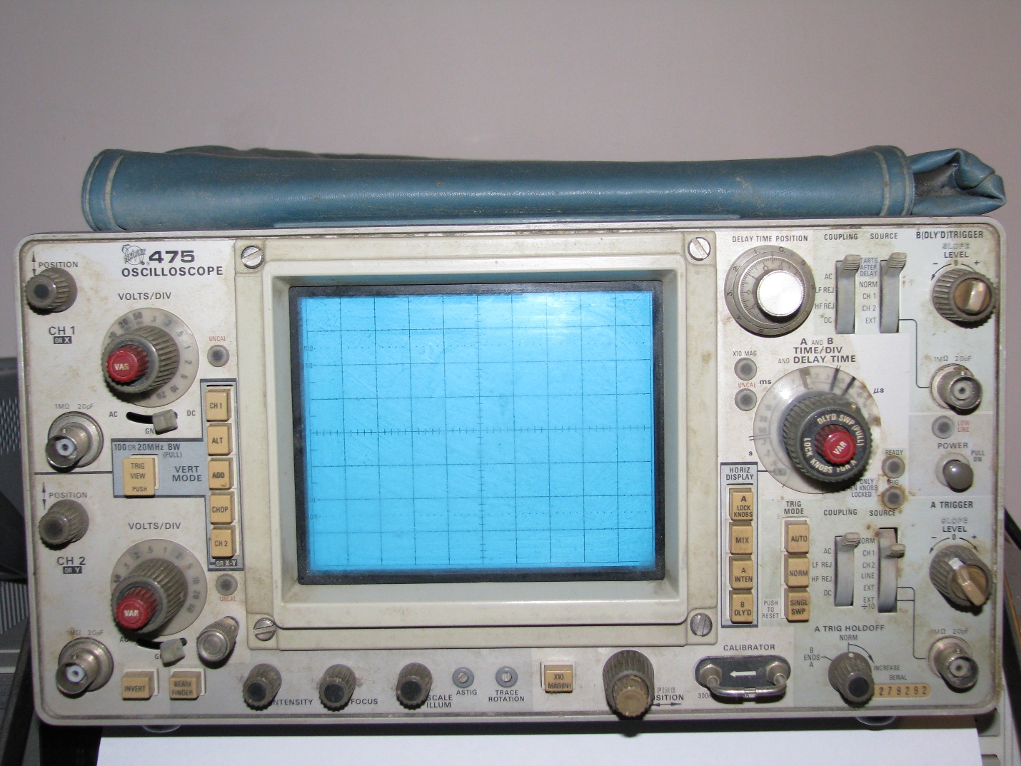
Figure 8 – Old analog scope
Of course, a digital scope is better. The price range for these type of scopes is quite large, and so are their features. However, even lower-priced digital scopes can offer the ability to capture a waveform for later analysis.
This feature is one of the most important aspects of digital scopes. The waveform does not need to be analyzed on the fly before it disappears.
With the judicious use of the scope trigger levels and modes such a single shot and hold-offs capabilities, it allows identifying issues that would otherwise be much harder if they had to be caught on the fly as with an analog scope.
Figure 9 shows an older generation digital scope with these basic functionalities.
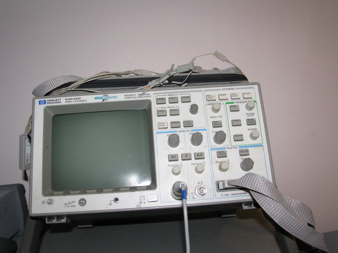
Figure 9 – Older, minimal-feature digital scope
Depending on what type of issues you expect to encounter, you might need to invest in a digital scope with lots more capabilities such as the scope shown below in figure 10.
Among the more prominent features of these types of scopes are: color screens, high bandwidth, math and signal processing capabilities, measurement, and infinite persistence modes.
For example, the scope could allow the computation and display of the sum or differences of captured waveforms from two channels. This can then be displayed and the RMS or time average values can also be calculated.
Using this, it is quite easy, for example, to determine the RMS and average current of a prototype as drawn from the DC supply.
Just insert a small current sense resistor on the high side of the supply, and hook up a channel on either side of this resistor. Then, set the scope to take the difference between the two readings.
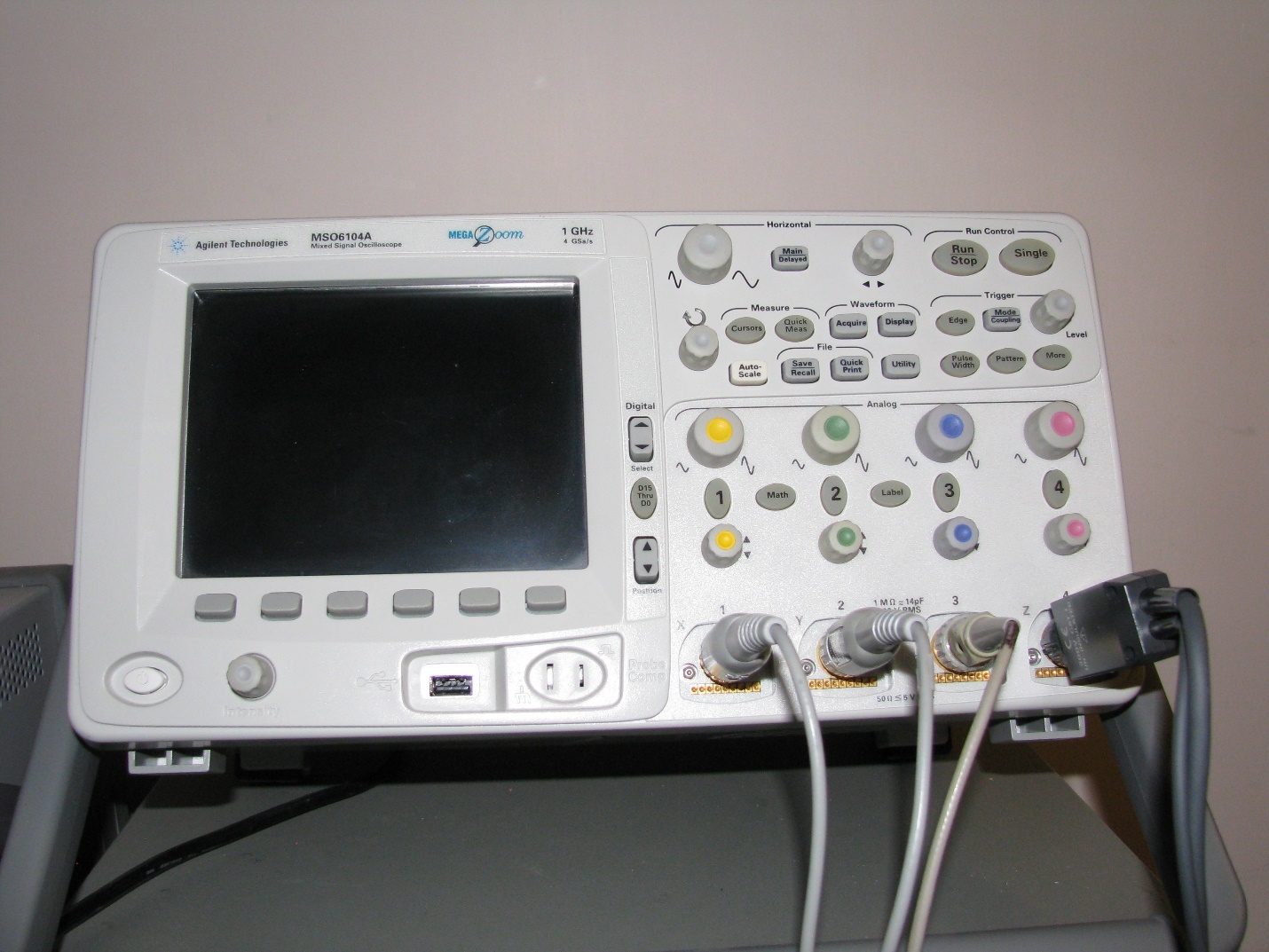
Figure 10 –Feature-rich digital scope with math capabilities and high bandwidth
A third channel can be set to view the attendant voltage droops. Since it is now possible to view all current spikes and voltage droops, it takes the guessing out of the design process to alleviate this.
Another example is setting the scope to infinite persistence. With the proper trigger level setting, it is possible to capture rare intermittent issues that may happen over extended time intervals.
These examples would have been very difficult to achieve without a digital scope. Of course, the display can be frozen, and saved; this facilitates documentation of what changes caused what effects, for further analysis and future reference.
Additional Instruments
The previous sections covered the basic test instruments. Depending on the type of designs that the lab is required to test and debug, additional test equipment will be required. In this section, I’ll present additional test equipment that should be part of more specialized electronics labs.
If you are testing analog circuitry, a good signal generator, or a function generator, is usually required (figure 11). Again, price and capabilities compromises can be tailored to fit testing needs.
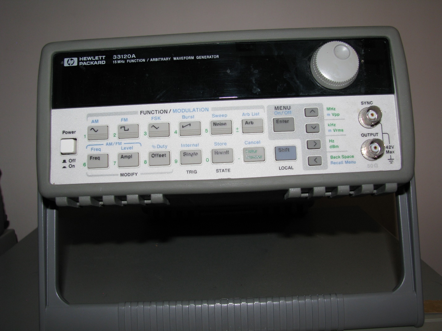
Figure 11 – A typical function generator
A good function generator can, for example, be swept over a large frequency range while keeping its output amplitude constant and low distortion. This can be used to check the frequency response of an audio circuit, for example.
Another useful tool is a thermal imager. This is particularly useful for validating designs with lots of components that are crammed in very tight spaces. Hot spots can develop, and this may cause the design to fail prematurely in the field, or, at the very least, to become off-calibrated over time.
Again, depending on the actual design, sometimes simply relocating some components can alleviate the issues. A thermal map of the design can show which components need to move, and where to move them to.
Figure 12 shows this type of thermal camera. Nowadays, there are cheaper handheld thermal imagers that could serve the purpose as well.
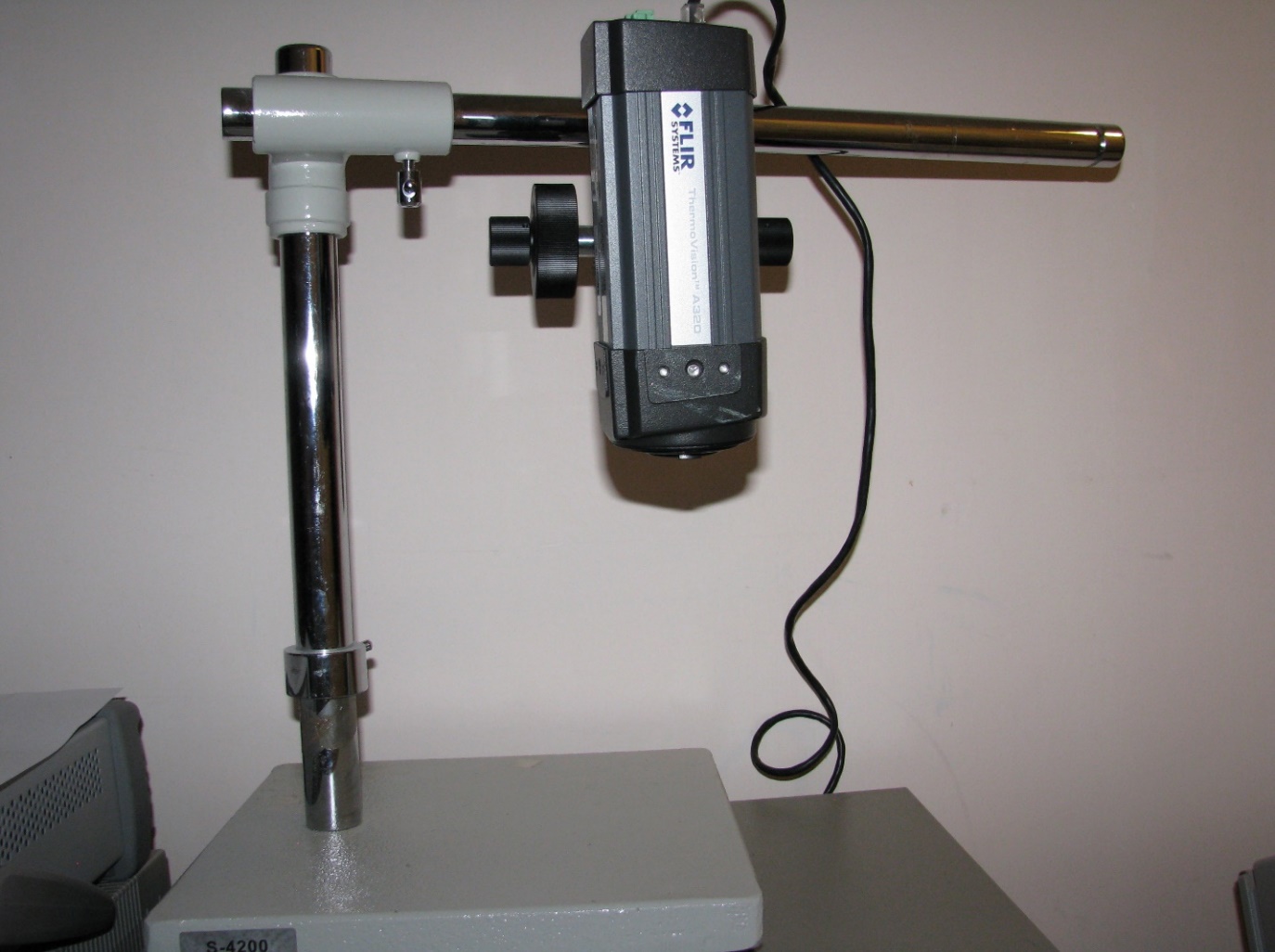
Figure 12 – Thermal camera
There are other specialized instruments that are helpful for certain types of design work.
For example, a digital lab will additionally have protocol analyzers and device programmers. A power supply lab, on the other hand, would have thermal chambers, power analyzers and electronic loads.
It is not possible to present every case here, but hopefully you now know how to set up your very own basic electronic lab.
Written by Shawn Litingtun.

thank you it was useful
excellent information for ece / eee engineers
Thank you, glad it was useful!
Great write-up, John. Thank you.
I would also recommend a LCR meter as entry lab tool to complement the DMM capabilities.