
An Introduction to Basic Electronics
If you are developing an electronics product, but you aren’t an electrical engineer, this article is for you. It provides an overview of all the basic electronic principles you need to understand in order to effectively manage your hardware startup.

Many entrepreneurs launching a new electronic hardware product lack the engineering skills to design their own product. So they instead choose to outsource most, or all, of the development.
That’s of course fine, and outsourcing is a fantastic way to fill in any gaps in your own skill set. Nonetheless, I believe that a basic understanding of electronics is still important for anyone bringing an electronic product to market.
As the founder of a hardware startup, you don’t need to know how to do everything yourself, but to be successful you should have a fundamental understanding of all the various tasks you must manage.
Whether you are a total non-techie, a new electronics maker, a software developer, or some other type of engineer, you will find this article helpful. I won’t be going into depth on any particular subtopic, but instead I’ll give you an overview of basic electronic principles.
Voltage / Current / Power
It all starts with voltage and current. The most common analogy for understanding voltage and current is water flowing from an elevated tank down through a pipe.
Voltage is represented by water pressure which is determined by the height of the water tank. The higher the tank, the higher the pressure. However, the arbitrary height of the tank isn’t what matters. Instead, what matters is the difference between the tank height and the ground height for the pipes.
The same is true of electrical voltage which is measured in Volts (V). Voltage is measured as a difference between two points. For example, when you say something is 5 volts that really means 5 volts with respect to ground voltage (which is 0 volts).
Electrical current, on the other hand, is equivalent to the amount of water flowing through the pipe, and is measured in Amps (A). It takes voltage to do the work in order to create this current flow. The more voltage that is applied the more current will be produced.
Power is the rate at which work is done and is measured in Watts. There are various equations for calculating electrical power but the easiest one to understand is that power is simply voltage multiplied times current.
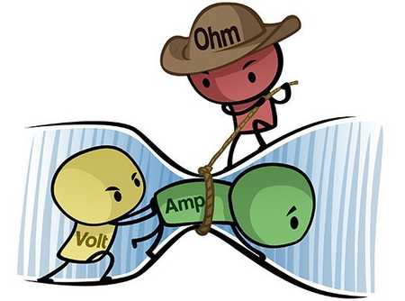
Cartoon illustration of voltage, current, and resistance – Provided by Build-Electronic-Circuits.com
Resistor
As the name implies, a resistor resists the flow of electrical current. The amount of resistance is measured in Ohms. A resistor is considered a passive component that consumes power that is dissipated as heat.
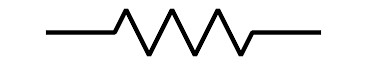
Symbol for a fixed value resistor
The power rating of a resistor determines how much power it can consume without overheating.
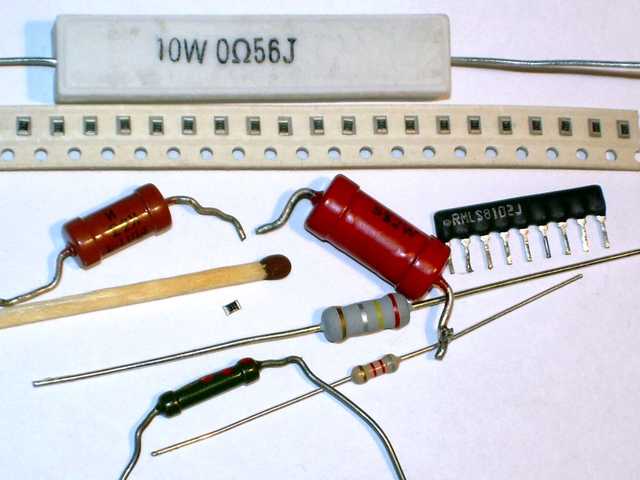 Examples of various styles of fixed resistors
A resistor is undoubtedly the simplest and most commonly used electrical component. Although they fundamentally only resist the flow of current, resistors have a wide variety of uses.
Resistors can be used to accurately divide down a voltage, or limit the amount of current that is allowed to flow. They can also be used for timing purposes and for filtering when coupled with a capacitor or inductor.
The most fundamental, basic equation used in electrical design is Ohm’s Law which defines the relationship between voltage, current, and resistance. This law can be written using the following equation:
Current = Voltage / Resistance
If there is only one electrical equation you should remember it’s Ohm’s Law. As an example of Ohm’s Law, let’s take a look at the simplest circuit possible consisting of a voltage source (V) and a resistor (R).
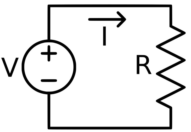
Simple circuit diagram showing a voltage source and a resistor
Let’s assume the voltage source is 3V and the resistor value is 100 ohms. How much current (I) will flow in this circuit?
Current = Voltage / Resistance = 3 V / 100 ohms = 0.03 A = 30 mA (mA = milliamps = thousandths of an amp)
Most resistances have a fixed, constant value but variable resistors are also available. These variable resistors are called potentiometers.
There are also specialized resistors such as a thermistor whose resistance varies with temperature. A thermistor can be used for measuring temperature.
Capacitor
A capacitor fundamentally stores electrical energy. In many ways, you can consider a capacitor as a rechargeable battery. Capacitors and resistors are easily the two most commonly used electrical components.

Symbol for a capacitor
Capacitance is the amount of energy a capacitor can store and is measured in a unit called Farads (F).
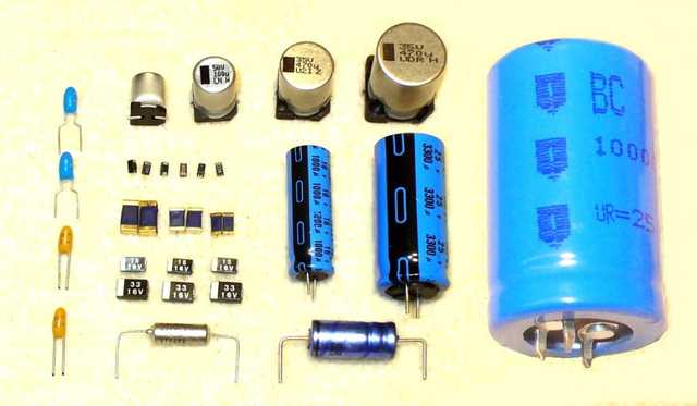 Examples of various capacitors
Capacitors have many purposes including energy storage, filtering, timing, and decoupling.
One fundamental characteristic of capacitors that make them useful for filtering is their resistance (technically called their impedance) decreases as frequency increases.
For example, for a non-oscillating DC signal a capacitor appears as an open switch with very high resistance. Whereas, for a high-frequency oscillating signal a capacitor is equivalent to a closed switch with very low resistance.
Decoupling is one of the most common uses for capacitors. Decoupling capacitors are placed near the power pin of integrated circuits (IC) to suppress coupling to other parts of the circuit through the power supply connection. These capacitors serve as a small localized reservoir of energy to supply the IC with current during fast, transient loads.
Inductor
An inductor is simply a coil of wire, and in fact they are commonly called coils. Like a capacitor, an inductor stores electrical energy. However, a capacitor stores this energy electrically, whereas an inductor stores it magnetically.

Symbol for an inductor
Resistors, capacitors and inductors are the three types of passive electrical components. However, inductors are not nearly as common as resistors and capacitors. The most common use of inductors is in a type of circuit called a switching regulator (see below). Inductors are also commonly used for filtering.
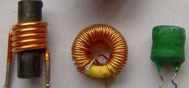 Examples of various inductors
The resistance (once again, really the impedance) of an inductor varies with frequency in the opposite way as a capacitor. An inductor appears as a closed switch to a DC signal, and an open switch to an high-frequency oscillating signal.
Semiconductor
A semiconductor is a material that is on the threshold between being a conductor and being insulator. The most common semiconductor material by far is silicon. Using semiconductor materials it’s possible to construct electrical devices that can operate as both a conductor and an insulator, just like a switch.
Diodes and transistors are two of the most important components created from semiconductor materials.
Diode
A diode is a type of semiconductor device. The most common function of a diode is it allows current to only flow in one direction.
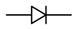
Symbol for a diode
For example, if you need to convert an Alternating Current (AC), which alternates the direction of current flow, to a Direct Current (DC) you would use a diode.
A special type of diode called a Light-Emitting Diode (LED) is also extremely common. In an LED, as the electrical current passes through the semiconductor diode it emits photons of light. This process is many times more efficient than light produced via an incandescent light source which wastes power as heat.
Transistor
Perhaps the most important technological advancement of the past century is the transistor. Transistors are the fundamental component behind any modern computer. A transistor is nothing but an electrical switch.

Symbol for a transistor
In digital applications they can be either off (0) or on (1). Put enough of these switches together and they can store data and perform complex calculations. A modern microprocessor may contain billions of transistor switches.
Transistors can also be used in analog applications where instead of being either fully on or off, they can be used to control how much current passes through them. For example, a common analog use of transistors is for amplifying a signal.
Integrated Circuit (IC)
Although transistors are the basic building blocks for complex computer chips, it is really the invention of the integrated circuit (also commonly called a microchip or simply just a chip) that makes it all possible.
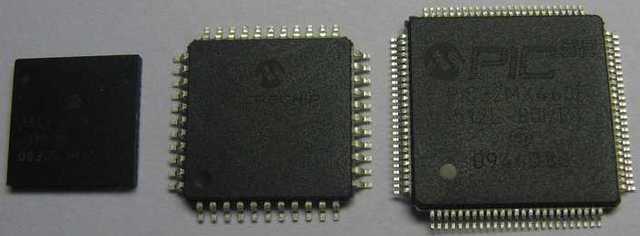 Examples of Integrated Circuits (ICs) which are also commonly called microchips
An integrated circuit is a single piece of semiconductor material (once again, usually silicon) that holds various electrical components (transistors, diodes, resistors, and capacitors).
Instead of a circuit made up of discrete components, an IC incorporates them all together. This allows signals between the components to travel much faster without any power loss.
You may be surprised to learn that my former employer, Texas Instruments, is the company that actually invented the integrated circuit many years ago. Jack Kilby was the TI engineer that invented this world changing technology.
Transformer
A transformer consists of two or more inductor coils. Energy is transferred from one coil to the other via a magnetic field. The most common use of a transformer is to step up or down a voltage. They are most commonly used in AC-to-DC converters.
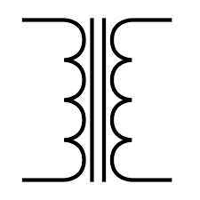
Symbol for a transformer
Linear Regulator
A regulator typically refers to a circuit that regulates a voltage. So for example if you have an input voltage that can vary from 6-20V you could use a regulator to produce a constant 5VDC output.
There are two broad types of regulators: linear and switching. A linear regulator is by far the easier type to understand and use.
A linear regulator uses a transistor like a faucet to control how much current is transferred to the output and thereby is able to regulate the voltage on the output.
The advantages of a linear regulator are the are cheap, easy to use, and provide the cleanest, noise-free supply voltage. Their primary downside is that in some applications they waste unacceptable amounts of power that is dissipated away as heat.
Switching Regulator
Compared to linear regulators, switching regulators are much more complex, require more components, produce more electrical noise, and cost more.
Switching regulators exist primarily for two reasons: they waste less power in most applications, and they allow you to do neat things like boost a lower voltage supply to a higher voltage.
For example, let’s say your product is powered by a 3.7V lithium-ion battery but a component requires a 12V voltage supply.
You could stack four batteries together to give you 4 x 3.7V = 14.8V, then regulate this down to 12V using a linear regulator. However, the better solution in most cases is to step-up the 3.7V voltage to 12V using a boost-mode switching regulator.
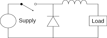
Circuit diagram for a step-down switching regulator
Switching regulators use inductors and capacitors to store and release energy at a certain rate. By varying the duty rate (percentage of on time versus off time) they are able to regulate an output voltage.
The condition in which their power efficiency comes into play compared to a linear regulator is whenever the input voltage is significantly higher than the output voltage.
In this scenario, a linear regulator may waste over half of the power that goes into it, whereas a switching regulator may only waste a few percent of the power applied.
Crystal
A crystal is a piece of quartz that operates on a physical principle known as the piezoelectric effect. When you squeeze a piece of quartz it electrically oscillates at a very precise frequency dependent on the mechanical pressure applied.
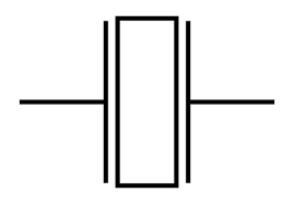
Symbol for a crystal
Both microcontrollers and microprocessors require highly precise timing in order to function. This is the purpose of a quartz crystal.
When precise timing isn’t quite as critical some microcontrollers offer the ability to instead use a less accurate internal oscillator comprised of a resistor and capacitor (called an RC oscillator).
Microcontroller Unit (MCU)
For modern electronic products, a microcontroller may be the most important component since it serves as the “brain” for the product.
A microcontroller contains a central processing unit (CPU), memory, and several peripherals all integrated on to a single chip of silicon. It is a highly integrated computer chip designed to pretty much stand on its own without the need for external support chips.
A microcontroller excels at interfacing with the external world via sensors, switches, lights, transducers, relays, motors, etc. Whereas, microprocessors excel at processing massive amounts of data very quickly.
Arduino is a family of development kits based on 8-bit microcontrollers from Atmel. An 8-bit microcontroller is sufficient for fairly simple applications.
But for more advanced applications requiring faster processing speed and more memory, a 32-bit microcontroller should be used. The most popular 32-bit microcontrollers are based on the Arm Cortex-M architecture.
Microprocessor Unit (MPU)
A microprocessor is necessary for applications that require fast processing of large amounts of data. At a fundamental level a microprocessor is no different than a microcontroller, they’re just faster, more complex, more expensive, and consume more power.
Unlike a microcontroller where both the processing unit and memory are integrated on the same chip, a microprocessor typically requires a separate chip for the memory. This gives you the flexibility to incorporate as much memory as required for your application.
But, the processor needs a very high-speed interface to any RAM memory, and this adds significant complexity to the PCB design.
The other big difference between a microprocessor and a microcontroller, is that a microprocessor almost always runs on an operating system (Linux, Android, Windows, etc.). On the other hand, a microcontroller simply executes the firmware code with no need for an operating system.
Schematic Diagram
A schematic is a conceptual engineering diagram that shows how all of the electronic components connect together. The various components are represented using the symbols shown throughout this article.
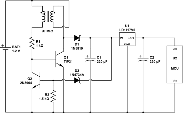
Example of a schematic circuit diagram
Printed-Circuit-Board (PCB)
A schematic is only an abstract diagram. To bring it into the real world it must now be turned into a Printed Circuit Board (PCB).
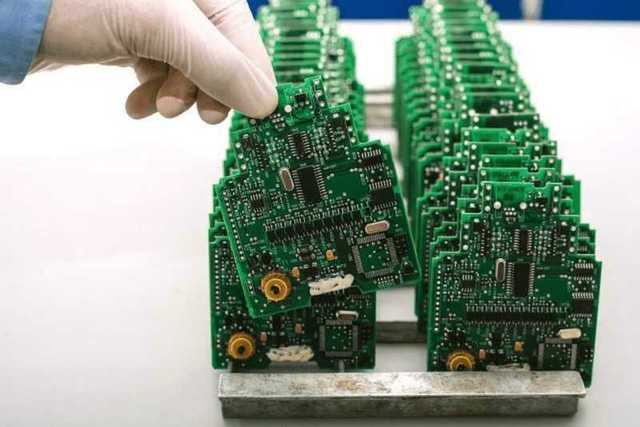 Tray of Printed Circuit Boards (PCB)
A PCB is the physical board that holds and connects all of the electronic components together.
First, the blank PCB is produced that includes all of the electrical routing and component landing pads.
Next, all of the various electronic components are soldered on the board usually using automated equipment.
The same software package that is used to generate the schematic diagram is also used to develop the PCB layout.
This software then performs all of the verification necessary to ensure that the PCB layout exactly matches the schematic diagram.
Electronic Module
An electronic module is a self-contained circuit designed to perform a specific function, and to be integrated into an existing system. One of the most common types of electronic modules is a wireless module.
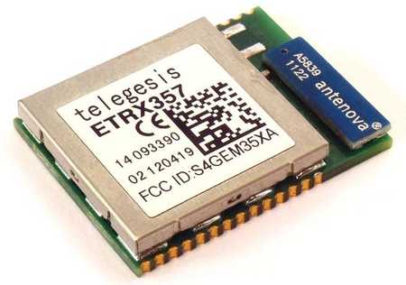 Example of an electronic module
For example, if you want to add WiFi to your design, then you have two routes. You can custom design the circuit necessary to implement WiFi. This circuit will be built around a microchip with a WiFi radio. The other option is you can instead use a WiFi module that is already a fully working circuit.
Modules are primarily used because they simplify the design. This means less time to market and lower development costs. Also, for wireless functions, modules can be used to reduce the cost for certifications such as FCC certification.
Breadboard
A breadboard is a solderless prototyping board that allows you to quickly and easily connect various electronic components including even some fairly simple microchips.
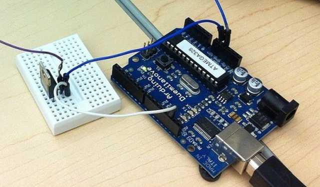 Breadboard circuit connected to an Arduino
Breadboards are great for simple projects that don’t operate at any significant speed. For example, if you wanted to build a simple circuit to flash an LED when you press a button, then you could use a breadboard.
But if you want to design a complex microprocessor circuit then a breadboard would not be appropriate.
Analog-to-Digital Converter (ADC)
We live in analog world, whereas computers operate in the digital domain. Analog refers to signals and information that are represented by continuously variable quantities.
For instance, in our analog world you could say it’s 1pm, 2pm or any value between those two times. On the other hand in the digital domain there are only two states: 0 (off) or 1 (on).
In order for a computer chip to process any analog quantity it must first be converted to a series of digital data. This is the purpose of an analog-to-digital converter (ADC). Many microcontrollers include built-in analog-to-digital converters, or they can be added as an external chip.
Digital-to-Analog Converter (DAC)
The opposite of an analog-to-digital converter is, you guessed it, a digital-to-analog converter. Many microcontrollers also incorporate built-in DACs, although not as commonly as with ADCs.
A common example of a DAC is for audio purposes. For example, when you talk on your smartphone, your voice is converted from analog to digital and then transmitted wirelessly in digital format to the receiving phone. The receiving phone then converts the digital data back into analog audio which is fed into a speaker.
A major advantage of transmitting data in digital format, versus as analog data, is that digital data is much less sensitive to interference and noise.
UART / I2C / SPI
Broadly speaking, digital chips communicate with each other using two methods: serial or parallel. Serial communication means all of the data flows sequentially through a wire, versus parallel communication transmits data through multiple wires simultaneously.
Most chips interface using serial methods because of the need for less wires which simplifies the design. The downside of serial communication is it’s not usually as fast as parallel communication.
For example, the connection between a microprocessor and any RAM memory must be very fast and therefore a parallel interface is typically required.
Universal-Asynchronous-Receive-Transit (UART) is one of the oldest and most common serial protocols. Asynchronous simply means no clock signal is used for timing purposes.
A UART interface needs at least two lines: receive and transmit. So data flows in only one direction on each of the two data lines.
I2C is a popular serial protocol that uses two wires: a clock signal and a bidirectional data line. I2C is considered synchronous since it uses a clock for timing. I2C is commonly used for interfacing all kinds of sensors to a microcontroller.
SPI is another very common serial communication protocol. Like with UART, SPI uses two data unidirectional data lines, but it is instead synchronous with a clock signal.
SPI tends to be the preferred choice when data speeds are more critical. For example, you may use SPI when interfacing a color display to a microcontroller. But you would likely use I2C to interface a temperature sensor to the microcontroller.
Conclusion
This article was designed to give you a very brief introduction to the most fundamental basics of electronics including a review of many of the electronic components available.
However, to be of any use these electronic components must be connected together to form electronic circuits. So be sure to now read my blog Introduction to Basic Electronic Circuits.

Thanks for this information
Very helpful post. Thank you.
Hi there,
This is an amazing post. I really enjoyed reading it and learned something. Thank you for putting so much time and energy into creating it.
Regards
Wow! Very informative and easily described. That helped me a lot
Hi Mr john it is one of the best article for beginners. Its short and very informative. Thanks for posting this
Thank you, I’m glad it was helpful!
Very informative article! Lots of information!
Me encanto lo que compartiste, sobre todo lo de schematic diagram. Lo voy a combinar con lo que estoy haciendo (http://bit.ly/2NjaQPR), para mejorar mis resultados
“…For example, if you want to add WiFi to your design, then you have two routes. You can custom design the circuit necessary to implement WiFi. This circuit will be built around a microchip with a WiFi radio. The other option is you can instead use a WiFi module that is already a fully working circuit. …”
Great article for all, even for experienced engineers in need of some immediate info…
Thank you Babu!
This article covers all the necessary things that I didn’t learn from my 4 years of college. Keep up the good work. Looking forward for more tutorials similar to this.
Thank you John
Awesome to hear, thank you!
Well presented John.
Thank you.
We now look forward to a case study, using all above items in a typical field application like a simple data acquisition/storage and transfer to remote device etc.
Csn
Thank you, and I will definitely consider your suggestion.
John
Dear John Teel!!
Very Good Day to You!
By chance, just came across this site.
Though since 1971 I am in Electronics (Communication / Navigation etc.) field but did find such simple & interesting piece of work. Only scrolled your article & found very nice and helping for the new comers to Electronics, as for the Basic Info is concerned.
Well done & Keep coming.
Best Regards
Abdur Rab
Thank you Abdur!
I am a software developer from China, ShangHai. I am quite interested in hardware development. This is article is quite useful for me. Thank you so much.
You are most welcome and I’m really glad you found it helpful!
This is very important basic information to me for making idea about design. Thank you Jhon
You are most welcome.