
Introduction to the STM32CubeIDE for STM32 Microcontrollers
Discover how to use the STM32CubeIDE to develop applications for STM32 microcontrollers. You will also learn why you want to develop an application using the STM32Cube IDE, and the pros and cons of using this method.

This article is about using the STM32CubeIDE to develop applications for STM32 microcontrollers. Why develop an application using the STM32Cube IDE, and what are the advantages and disadvantages of using it?
The STM32CubeIDE is a complete development system to develop code for almost all STM32-based microcontrollers from ST Microelectronics. As the name suggests, it is an Integrated Development Environment (IDE) that essentially includes the STMCubeMx GUI HW configuration tool, and a full compiler.
It can be used as a development platform for all STM32 MCU’s, whether it is on a development board such as from one of ST’s Nucleo or Discovery family, or a custom-designed board.
Another advantage is that it allows for much better control of the MCU. Compared to Arduino, the user is no longer limited to just what functionalities Arduino provides, and what MCU’s it has been ported to.
However, this flexibility comes at a price.
For one thing, using the STM32CubeIDE locks the user into ST’s ecosystem. In other words, it is geared toward the STM32 family of MCU’s.
ST does have a very large selection of STM32 MCU’s though, and this approach means that once an application is written, it is relatively easy to port that to another, more powerful, member of the STM32 family, should the need arise.
Another is the development code has to be in C/C++. In other words, some of the higher level HW abstractions from Arduino, for instance, are not available.
It is not as simple as calling Serial.begin or DigitalWrite functions as in Arduino. The actual UART, or GPIO port, has to be properly initialized first.
This is where the GUI configuration tool helps. Still, this also means that the user has to be quite aware of the MCU internal architecture and the actual HW design that this MCU is part of.
As will be seen later, knowledge of the appropriate ST’s HAL API also helps. This Hardware Abstraction Layer Application Programming Interface can greatly ease the transition from, again, Arduino to using STM32CubeIDE.
For the purpose of this article, an STM32 BluePill board will be used as the base HW. This is readily available, and serves the purpose of an introduction to STM32CubeIDE.
Other than the actual BluePill, a device programmer will also be required. For this, one of the STLInk V2 clones will be used.
Figure 1 shows an example of both the BluePill and the ST Link V2 clone. Since the intent of this article is to introduce the STM32CubeIDE, and not code development, the application example is the simple “Blinky”.
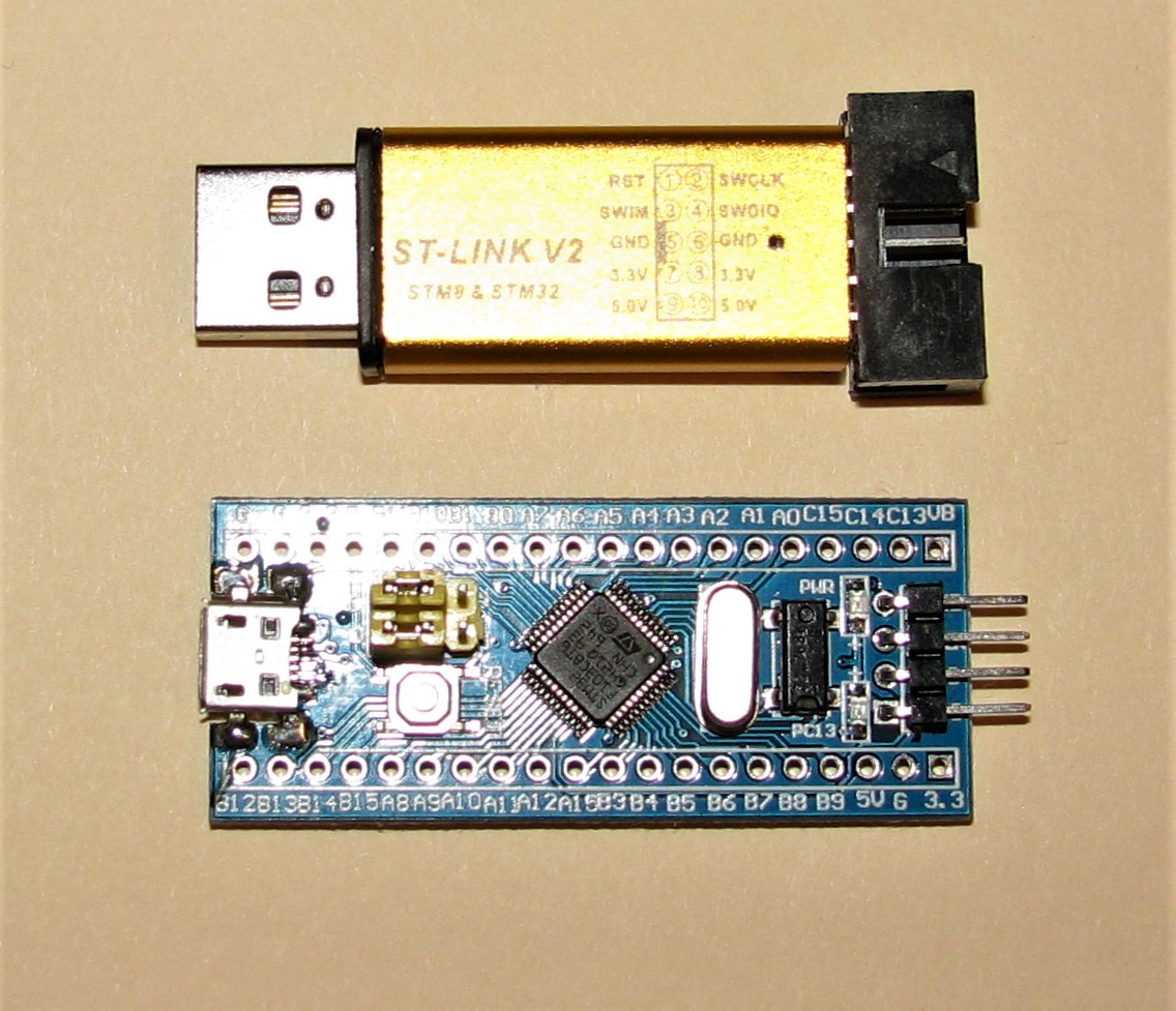 Figure 1 – Example of a BLuePill and ST Link V2 device programmer clone
Configuring the Hardware
The first thing to do is to install STM32CubeIDE. This can be downloaded here. Note that registration is required.
After installation, you can startup the application. Select from File-New-STM32 as shown in Figure 2. After a little while, the device selection screen shown in Figure 3 will appear.
Here is where knowledge of the actual HW is required. Figure 4 shows the schematic diagram of the STM32duino BluePill module. As can be seen, the MCU is a STM32F103C8T6. So, this is what is selected.
[Click on any of the screen shots below to open hi-res version]
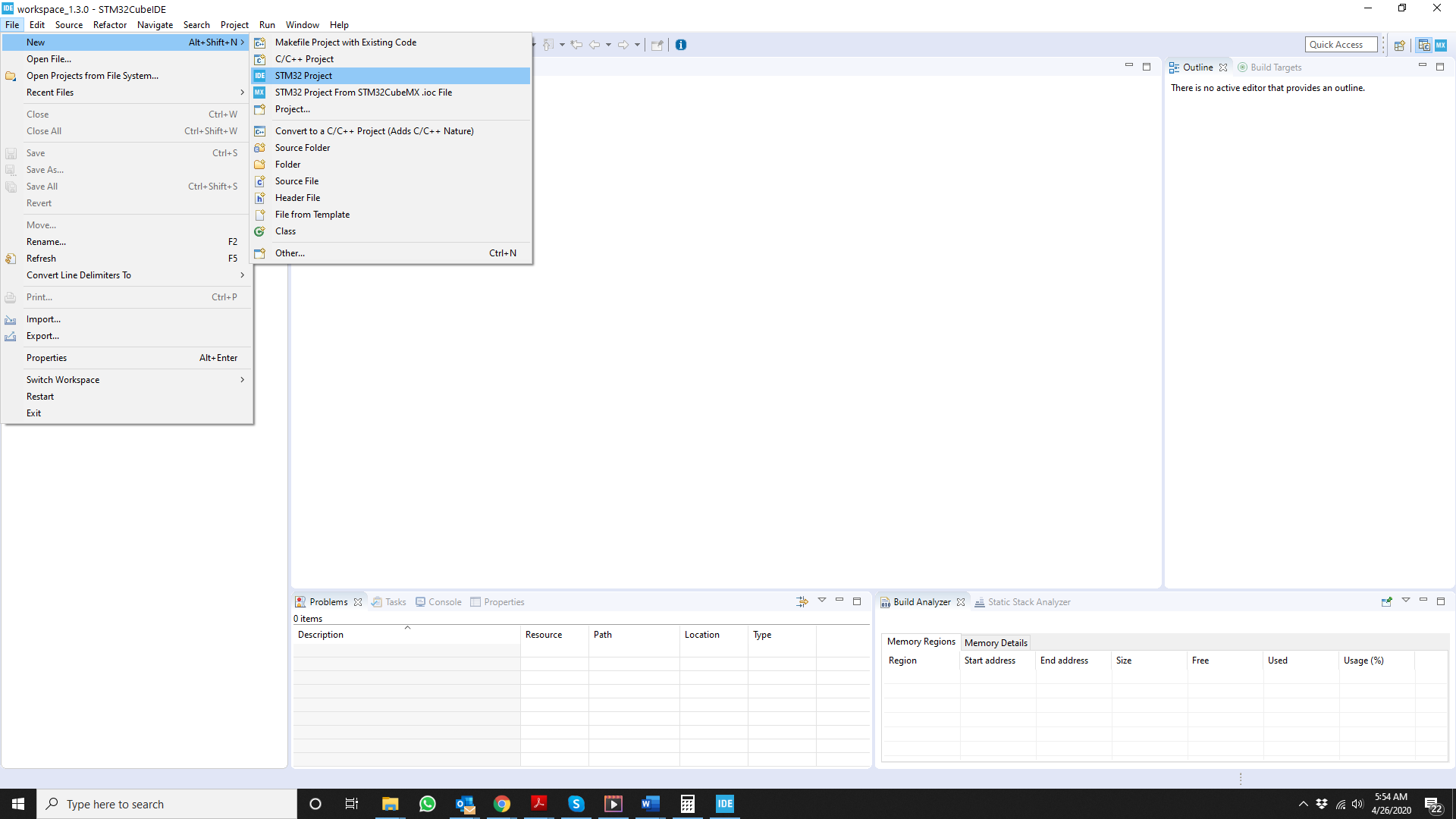 Figure 2 – initial screen of STM32Cube IDE showing selection drop-downs for a new project
<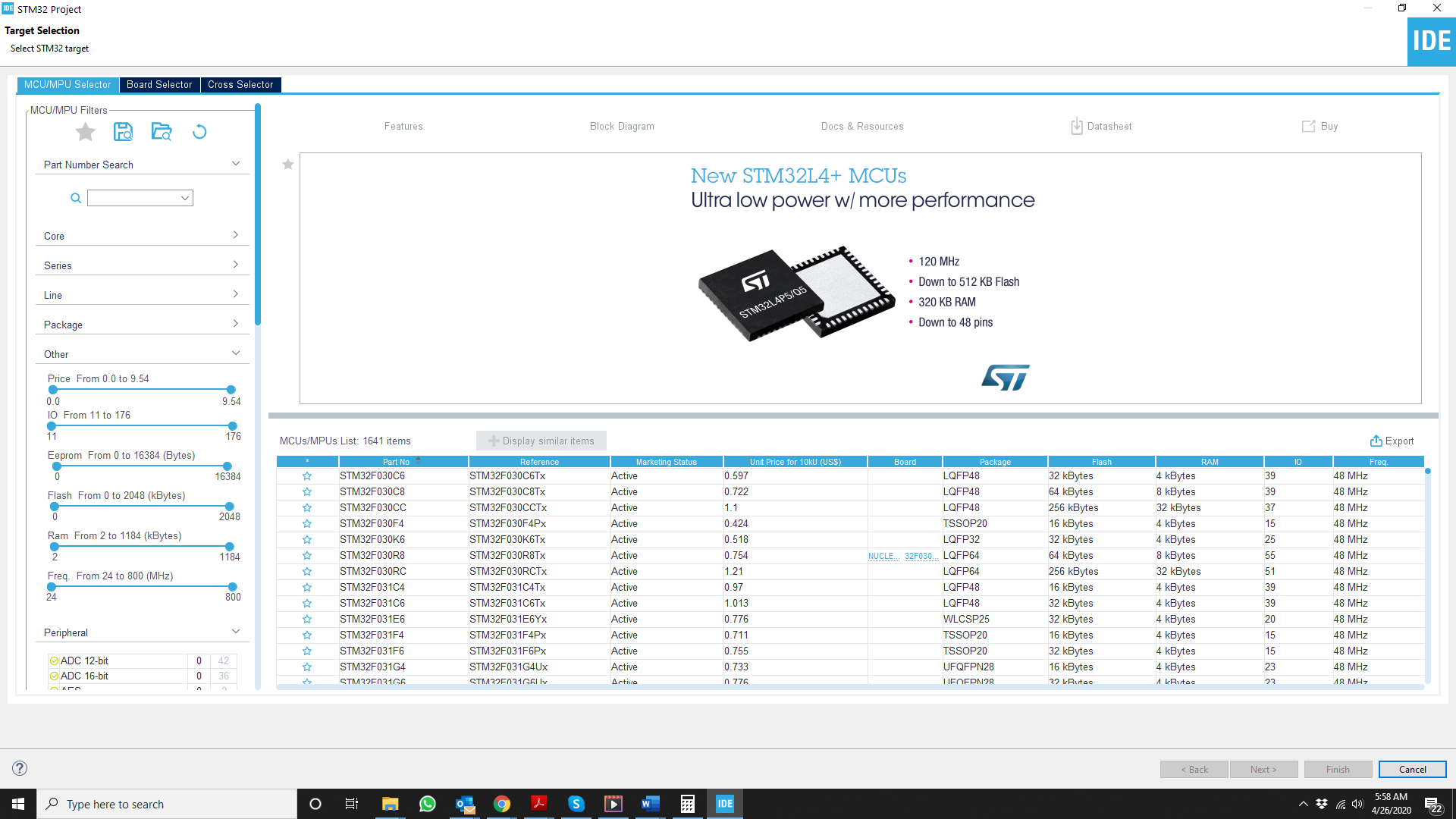 Figure 3 – Device selection screen
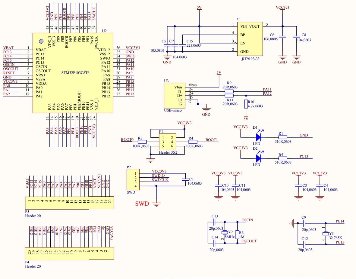 Figure 4 – STM32Duino BluePill schematic
The next screen requests a name for the project, and also some information about the type of project. In this case, as shown in Figure 5, the project will be an executable called Blink, and it will be done using C.
After a while, and answering “yes” to the pop-up about STMCube, the screen shown in Figure 6 will appear. This is the device pinout view screen. It allows the user to choose the function of the MCU pins.
The pins of the STM32 MCU, like most other MCU’s, can be configured for many uses such as GPIO, ADC, Timer and others. Here again, knowledge of the actual HW is needed to properly configure the pins for their intended use in the HW.
First, select the proper clock source for the MCU. By default, the MCU uses its internal RC oscillator. However, in the STM32duino BluePill, the clock is actually an external crystal.
Again referring to figure 4, the BluePill external crystal frequency is 8 MHz. In keeping with the most commonly used clock frequency for the BluePill, the internal clock frequency will be set to 72 MHz.
First go to the Pinout & Configuration tab, and select RCC; this stands for Reset and Clock Control. Now in the panels that appear, choose the High Speed Clock (HSE) to be “Crystal Ceramic Resonator”.
Next, select which pins the Crystal is going to be attached to. Even though the schematics in figure 4 label these pins as OSCIN and OSCOUT, they are, in fact, PD0_OSC_IN and PD1_OSC_OUT. Just left-click on PD0 and PD1, and select their functions to be OSC_IN and OSC_OUT respectively. This completes the setting of the pins for external crystal usage.
The next part is to set up the clock frequency. Click on the Clock Configuration tab, and a screen like that shown in figure 8 will appear. Values are entered directly in the various boxes.
Since the external crystal clock is 8MHz, just make sure that this is set to 8. Next select HSE, or High-Speed External, in the PLL source MUX. Then, set the PLL MUL to 9.
This essentially multiplies the input clock by 9, giving it a value of 72MHz. Now, set the System Clock Mux to PLLCLK. That is, tell the MCU that its clock source will be the output of the PLL.
There are many other options. For example, the CSS can be enabled. CSS stands for Clock Security System. If enabled, then a non-maskable Interrupt is generated if the external clock fails.
Otherwise, the MCU switches to use its HSI, or High Speed Internal, clock. In this example, this will not be enabled. The confusing part is the box will show “Enable CSS”, but it is actually not enabled.
If enabled, the box will show “CSS Enabled”. Finally, the APB1, or Advanced Peripheral Clock 1, prescaler should be set to /2 since the maximum APB1 clock frequency is 36MHz. This is the clock source for the UART, for example.
The other options allow the peripherals to be clocked at frequencies other than core clock. This can be used to reduce power consumption, for instance. However, in this case, the rest will be left as is. Figure 8 actually shows the proper values as just described.
Since the application requires blinking the built-in LED, the pin driving the internal LED needs to be set up now. Looking at the schematic diagram of figure 4 once again, it is seen that the internal LED is driven by PC13. So, this pin has to be set to be a GPIO output pin.
Go back and click on the Pinout & Configuration tab. On the pinout diagram, left click on the PC13 pin, and select GPIO_Output. Right click on the same pin, and select “Enter User Label”. Enter a name such as “LED” for this pin.
Now, select System View on the main window, and select GPIO. The screen will look like that shown in Figure 9. In the GPIO Mode and Configuration window, various settings for the GPIO pin can be selected.
As shown in Figure 9, the initial output is Low, the mode is push-pull and there is no pull-up or pull-down. That should be fine for this application, but just be aware that these settings can be changed to suit the application. This completes the required settings for this application.
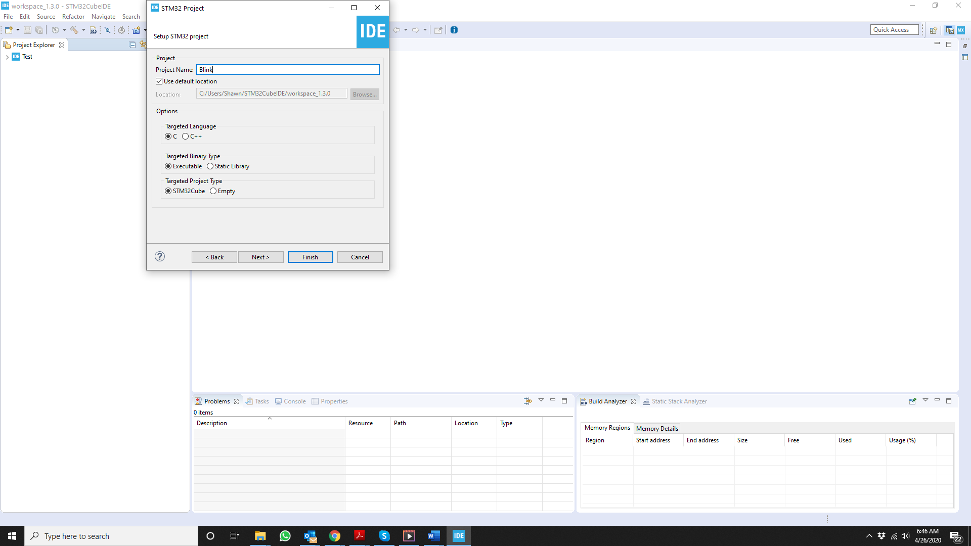 Figure 5 – Project information screen
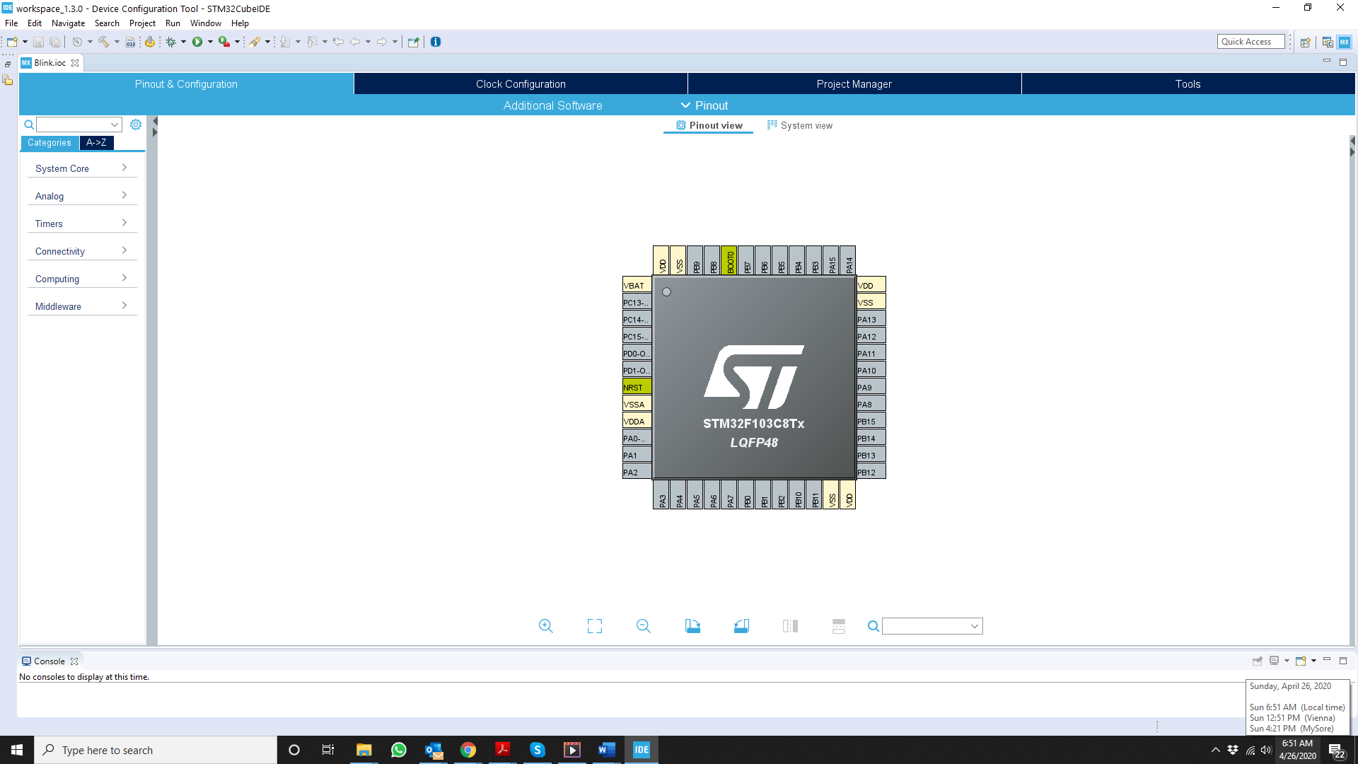 Figure 6 – Pinout view of the STM32F103C8Tx MCU
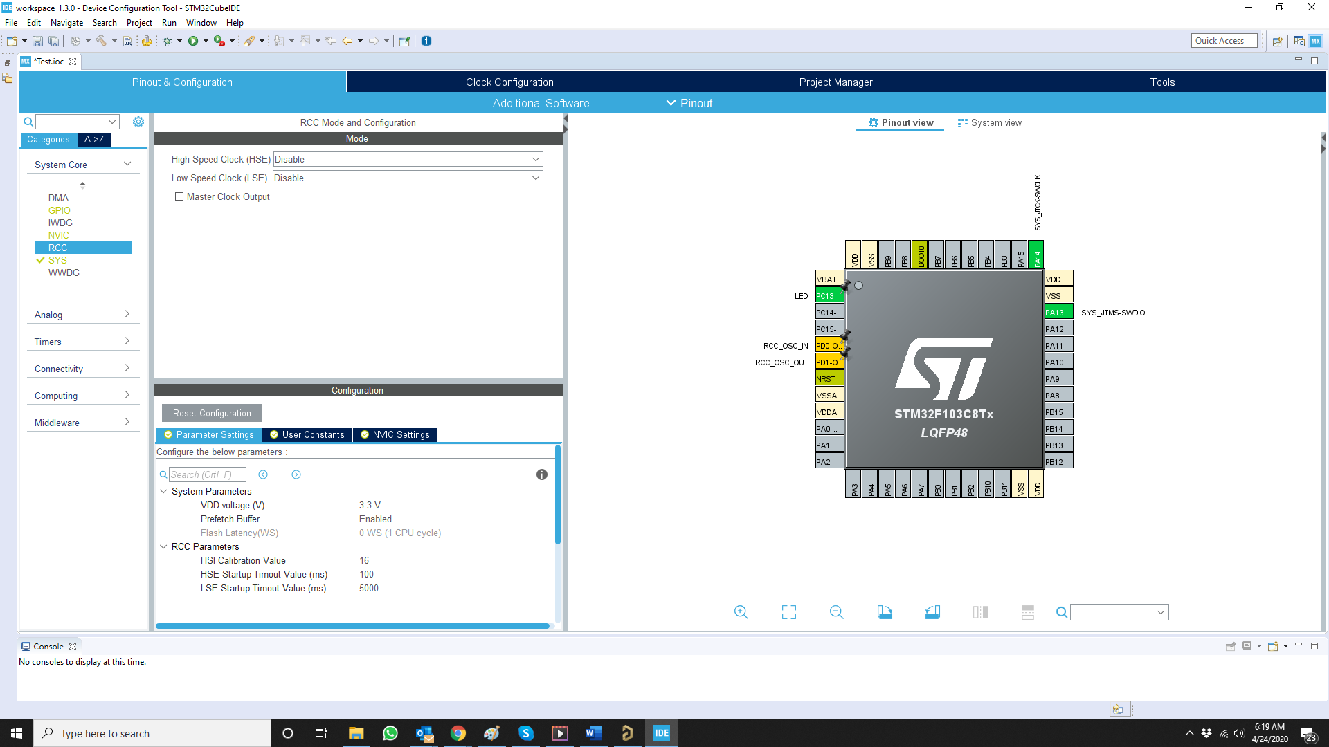 Figure 7 – Pinout & Configuration tab for selecting external clock source
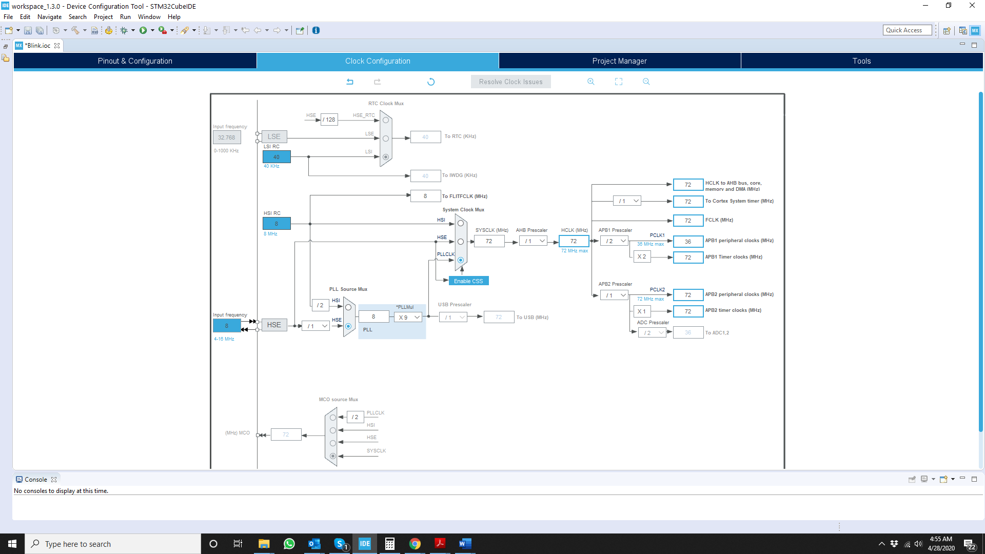 Figure 8 – Clock configuration screen
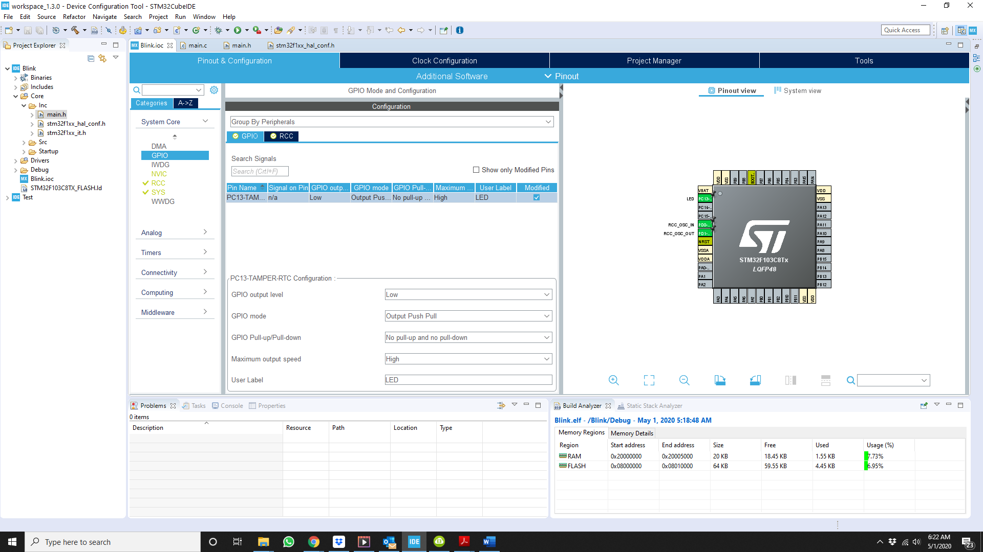 Figure 9 – System view screen
Code
So, what does all the configuration in the previous section do? It allows the automatic generation of initialization code for setting up the clock and GPIO.
Just go the “Project” tab, and click on “Generate Code”. A pop-up progress window will appear, and after it is done, navigate to the “Project Explorer” tab.
From there go to “core”, then to “Src”, and click on main.c. This will open up the main.c file in the main window. As can be seen in figure 10, lots of code has been generated already.
Scrolling down this window to the int main(void) function, it is seen that it already calls three functions: HAL_Init(), SystemClock_Config(), and MX_GPIO_Init(). The actual functions are defined further down in main.c. These are the HW setup functions that were automatically generated based on the user configurations entered previously.
Also note that there are various sections with comments that start with something like /* USER CODE BEGIN WHILE */, and /* USER CODE END WHILE */. The space between any comments that are bracketed by comments that start with “USER CODE …” is where the user is expected to enter the application-specific code. This is shown in figure 11.
In this article, some code will be entered in the sections defined in the previous paragraph. Before getting to that, open the main.h file, and locate this section:
/* Private defines ———————————————————–*/
#define LED_Pin GPIO_PIN_13
#define LED_GPIO_Port GPIOC
/* USER CODE BEGIN Private defines */
/* USER CODE END Private defines */
Using the “LED” label provided earlier, the code generator has already defined some names to GPIO_PIN_13 and the port it is on. In this case, LED_Pin is GPIO_PIN_13, and LED_GPIO_Port is GPIOC.
Go back to main.c, and insert the following two lines between /* USER CODE BEGIN WHILE */, and /* USER CODE END WHILE */, as shown in figure 12.
HAL_Delay(500);
HAL_GPIO_TogglePin(LED_GPIO_Port, LED_Pin);
The first line is a delay of 500ms, and the second line simply toggles the LED pin as defined earlier. Since this is in the main loop, it is repeated forever, and thus the LED blinks forever.
The more important part of the code is the actual functions that were called in the main loop. These functions are part of the HAL API that is already included in the application that was just developed.
Understanding this HAL API, and knowing what is available, and how to call the different HAL functions goes a long way toward making code development for STM32 MCU’s easier and faster. Here is a link to the HAL API.
As a side note, notice how this blink function is different from the typical Arduino blink implementation due to the single call to the HAL_GPIO_TogglePin() function.
Below is the actual section on this function from the HAL user manual:
HAL_GPIO_TogglePin
| Function name | void HAL_GPIO_TogglePin (GPIO_TypeDef * GPIOx, uint16_t GPIO_Pin) |
| Function description | Toggles the specified GPIO pins. |
| Parameters | GPIOx: Where x can be (A..K) to select the GPIO peripheral for STM32F429X device or x can be (A..I) to select the GPIO peripheral for STM32F40XX and STM32F427X devices.
GPIO_Pin: Specifies the pins to be toggled. |
| Return values | None: |
Scanning through this section of the HAL User Manual, there are many GPIO-related functions, including this one, that are not available in the native implementation of Arduino.
 Figure 10 – main.c
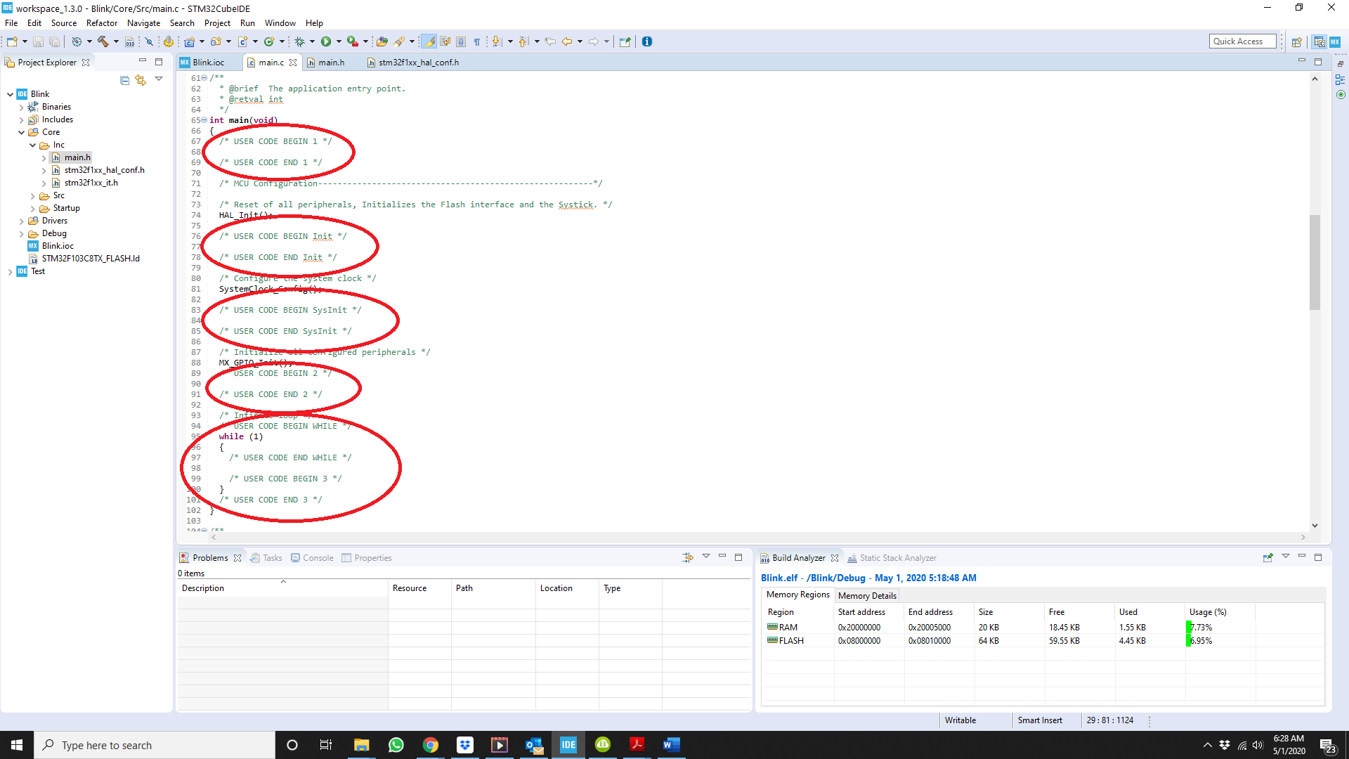 Figure 11 – main.c areas where the user can enter code
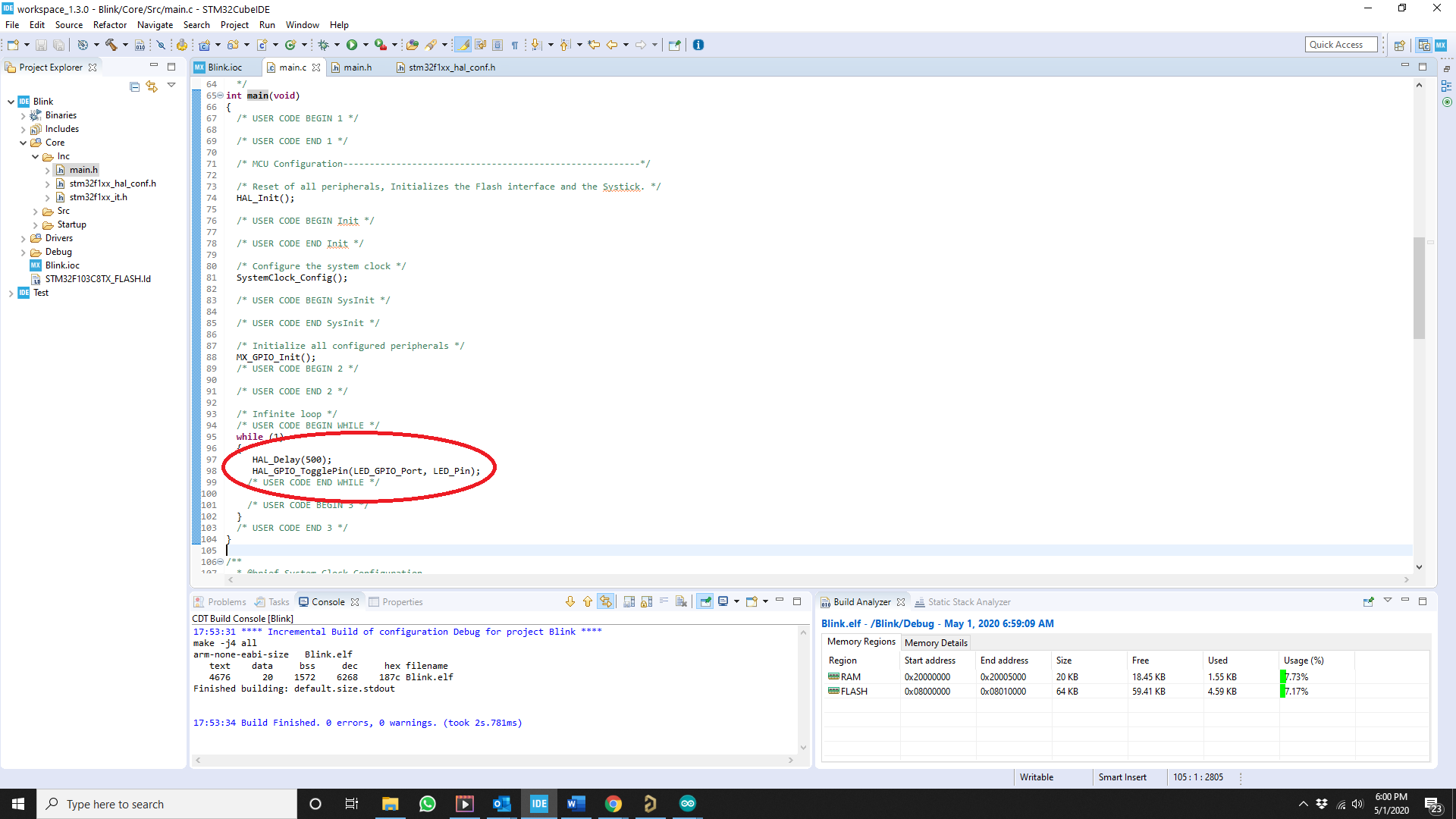 Figure 12 – Added code to while (1) main loop
Compiling and loading
To compile the code, simply go to the Project tab, and select Build All. Assuming there are no compile errors move to the Debug folder and locate the .bin file.
As shown in figure 13, this is Blink.bin. This is the file that has to be loaded to the actual STM32 MCU. The actual loader can be the STM32 ST-Link Utility.
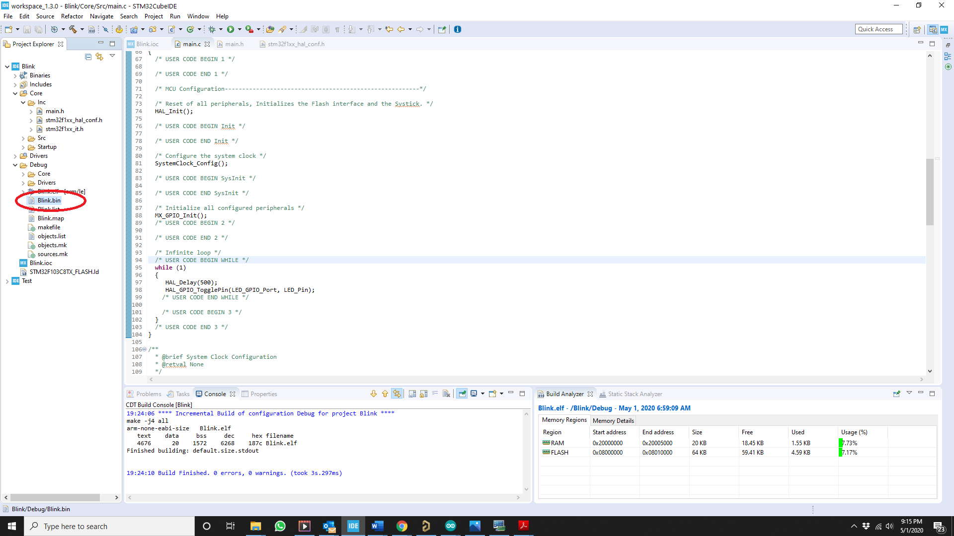 Figure 13 – Locating the .bin file
The actual process of loading a binary file into the STM3Bluepill is fully described in many other places, so I’ll just provide a summary.
Here are the steps:
- Connect the following pins of ST-Link V2 to the STM32duino: 3.3V, SWDIO, SWCLK and GND.
- Set the STM32duino to DFU, Device Firmware Upgrade, mode by moving the BOOT_0 jumper to the 1 position.
- Plug in the ST-Link V2 and start the utility. A screen looking somewhat like figure 14 will appear.
- Connect to the STM32duino, and then flash the code. Address of 0x800000 is fine as is.
To test, put the STM32duino back to user mode, and simply reset by depressing the RESET pushbutton. The LED on the board should flash, indicating a successful code download.
 Figure 14 – ST-Link utility screen
Conclusion
It has been a rather long and tedious process to get the STM32duino to simply blink its LED. Obviously, for this particular task,
Although its not necessarily the best way to achieve a blinking LED, I hope this example has illustrated how to set up and use the STM32CubeIDE
Once you understand this process, you can use any STM32 MCU for any HW design, with full access to its internal peripherals. This really opens up new possibilities that are not typically offered by more restricted development systems.
Written by Shawn Litingtun.

I followed these steps and now I can’t connect to the blue pill to download a new program
Great article.
That would be great if you can make an article about how to use machine learning on Microcontrollers in general. A big picture for people who do not know about machine learning
What is the difference between work with STM32CubeIDE and Keil uVision 5?
can we do debugging our code on STM32CubeIDE with ST-Link/v2?
Yes, it works.