The Beginner’s Guide to Designing with the dsPIC33 Microcontroller
How do you choose the best microcontroller for your new tech product? Keep reading to discover the advantages and disadvantages of different types of microcontrollers.
Technical Difficulty Rating: 7 out of 10
This is a guest post by Roberto Weiser of Developpa.io.
If you are designing an electronic product, chances are that it will have a microcontroller (MCU) embedded into it.
In order to control, process, easily change parameters of the design on demand and keep the design tidy and relatively low complexity, it is unpractical to approach a solution using purely discrete analogue and digital components.
For this reason, a natural choice is the use of a microcontroller. A microcontroller is basically a computer shrunk to a chip. It contains a CPU, memory, I/O pins and peripherals, all in a single package.
There are many microcontrollers’ manufacturers and architectures in the market, some that are most common in the market and the “student and hobbyist” sector are:
- PIC from Microchip
- AVR from Atmel
- 8051 from Intel
- ARM from different manufacturers
Each different type has its own pros and cons, and some of them are very similar as well. In the end, the choice of the microcontroller comes down to the specifics of the application and the familiarity the programmer has with the MCU.
The dsPIC33E
Before the Arduino, Microchip PICs were the microcontroller of choice for many hobbyists and makers. It’s extensive community, cheap price and versatility made it a very attractive option for first timers in the world of embedded electronics.
As MCUs became more powerful, and the industry demanded more from them, manufacturers came up with ideas such as integrating an MCU with special hardware and functions to perform real-time digital signal processing.
Microchip created its own family of these devices and baptized them as dsPICs. They integrated all the well-known features of the PIC MCUs with the horsepower and architecture required to perform complex mathematical operations in real time.
They also created a nice DSP library that makes life a lot easier when implementing DSP operations such as digital filters, Fourier transforms and automatic gain control.
In this article, we will learn how to make your first design of an electronic device with the dsPIC33E. This article is divided into 3 sections:
- Hardware considerations: first, we will explore the electronic components and connections required for the dsPIC33E to work.
- Firmware configuration: this is the essential code and configuration that the dsPIC33E needs in order to run.
- Code examples: we will look at some simple code that you can implement to perform some basic functions.
Caution: All recommendations and code examples have been tested with the dsPIC33EP128GP502. If you are implementing a different device, please check its datasheet and product information as there might be some minor differences.
Hardware Considerations
In this section, we will review all the essential connections the dsPIC33E needs to work properly and some other design advice for implementation.
The dsPIC33E needs some components and connections in order for it to function as described in the datasheet:
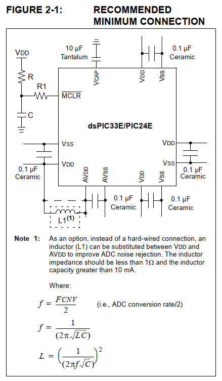
These connections are basically connecting your power supply to the different Vdd (logic/digital supply) and AVdd (analogue supply) pins as well as the GND of the power source.
Your power source could be 5V or 3.3V depending on your choice of MCU, normally for dsPIC33E’s 3.3V is the norm.
Another important aspect is to add capacitors in parallel between the supply and the power pins. These capacitors are very important as they keep the voltage stable at the MCU supply in order to avoid malfunctioning or a reset event because of undervoltage.
These capacitors must be of low ESR so they can react quickly to the power supply variations. A standard choice would be a 100nF ceramic capacitor with X7R type dielectric and a rated voltage higher or equal to 16V.
The dsPIC33E also has an internal regulator that uses the capacitor placed at the pin VCAP for regulation. This capacitor should be ceramic low ESR with X7R dielectric type and a capacitance of at least 10uF and rated voltage of 16V or higher.
The /MCLR pin also needs to be connected with a pull-up resistor of 10Kohms to Vdd. This pin is capable of resetting the dsPIC33E if pulled low. It is normally used for programming the dsPIC33E but it can also be used to reset the MCU with another circuit.
The capacitor on the /MCLR pin is used to keep the voltage stable so the device does not reset from a power supply drop. Note that this capacitor should only be placed during the manufacturing stage when the dsPIC33E has been pre-programmed.
If you place it and try to program the dsPIC33E, it will not work as the capacitor will form a filter with the resistor and distort the command signal from the programmer.
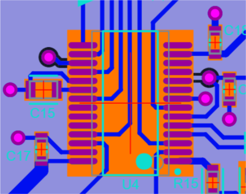
Make sure all capacitors are as close as possible to the Vdd pins and with a direct connection to GND as shown in the PCB layout below.
Programming and Debugging Interface
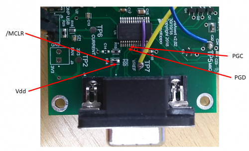
To program the dsPIC33E, you need 3 mandatory connections from the MCU to the programmer: /MCLR, PGEDx and PGECx.
The dsPIC33E have the versatility of having at least 3 different positions in the pinout where you can connect the PGEDx and PGECx.
You should choose the best pair (1,2 or 3) according to where you will place the debugging connector on your PCB.
For this design, the PGED3 and PGEC3 pins were chosen as they were closer to the programming connector.
Apart from /MCLR, PGEDx and PGECx, you need to add Vdd (3.3V only) and GND to the programming connector.
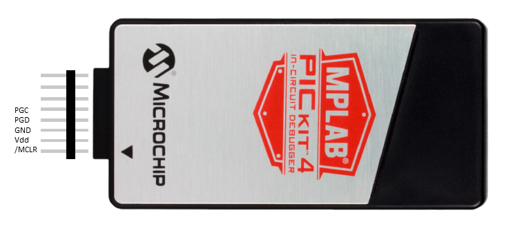
A cheap and accessible programmer for the PIC microcontrollers is the PICKit4. You can buy it from many online shops and it costs around 50 USD.
To connect the programming connector to the PICKit4, you can use the following wiring diagram:
ADC pins
Is your device sensing any analogue signal such as audio, temperature, current or voltage? If so, you will need to use the ADC.
MCU ADC pins are labelled as ANx, and they will sample any voltage that you feed them that goes from the range of AVdd-AVss, which in most applications is Vdd-GND or 3.3V-0V.
Some care must be taken with analogue signals in order to ensure an appropriate reading and not overload the pins.
It is good practice to place an RC (resistor+capacitor) low pass filter before the ADC pin. Apart from filtering unwanted high frequencies signals, the capacitor provides a low impedance source for the ADC to sample the signal and the resistor can limit any high currents that could appear from an overvoltage event.
If you are measuring DC or low-frequency signals, a combination of 220ohm-470ohm resistor in parallel with 22nF-47nF capacitor should suffice.
External Oscillator
The dsPIC33E counts with an internal oscillator of 7.37MHz that can go as high as 70MHz. using an internal PLL. To use this oscillator you don’t need to add any extra hardware.
This oscillator has a tolerance of +/-2% that varies mainly with temperature. This means that if your application requires high precision when it comes to timings or generating signals, you might need to consider adding an external oscillator.
This can be done in two ways.
1) External crystal with internal MCU oscillator circuit
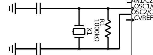
For this configuration, 4 components are necessary. The crystal, 2 capacitors and 1 resistor. These components should be connected the following way to pins OSC1 and OSC2:
To select the value of the capacitors, perform the following calculation:
C_XTAL = 2*(Cload-Cstray)
Where Cload is the capacitance of the crystal given on the crystal’s datasheet and Cstray is the capacitance introduced by the PCB, which is normally between 2pF to 5pF.
Make sure the selected capacitor is ceramic of NP0/C0G dielectric type and are placed next to the crystal.
2) External oscillator
Maybe you have more than one clock-dependant IC in your circuit and you want them to both run at the same clock in order to avoid any timing mismatches.
If that’s the case, or you just want an external oscillator for any reason, you can easily design one and then connect its output to the OSC1 pin.
Overvoltage Protections
The MCU is quite a delicate IC. Think about it, it is not an opamp, it is a mini computer! As a designer, you should always think about keeping the MCU running in “good conditions”
What is meant by good conditions is that you stay within the specified limits written on the datasheets, away from heat and power it with a stable power supply.
One rule to avoid the MCU from getting cooked is to never feed a voltage to its inputs bigger than Vdd.
Some pins from the MCU are protected against overvoltage but they are mostly there for transient events. If you have a signal that is bigger than Vdd and you need to interface it with the MCU, make sure to scale it down or limit the voltage it can reach first.
This can be done with a voltage divider for an analogue signal, via a Zener diode with a current limiting resistor for a digital signal, or a level shifter chip.
Internal Pull-ups/down
The digital I/O’s can be configured to have an internal pull-up/down resistor.
This is very useful to save on external components when you need to have a constant pull-up/down.
For example, if your device has a pushbutton that requires a pull-up to Vdd, you can configure the port as digital input with pull-up, this way you save money and space by not placing the external resistor.
Driving External Loads
The dsPIC33E I/O pins can source and sink a max of 5mA which is not much. Other MCU’s can do more, however, this should generally be avoided.
If you drive a load such as an LED or optocoupler with an MCU, the current required to turn on these components is passing through the dsPIC33E internal circuits, therefore, some dissipation is happening on the MCU case.
It is better to have external transistors controlled by the MCU so all the dissipation occurs outside and avoid any overcurrent possibility on the dsPIC33E internal power rails.
Getting Started with the Firmware
In this section, we will learn how to configure the dsPIC33E using Microchip tools and software. Then, some code will be shared for basic applications.
Programming Environment
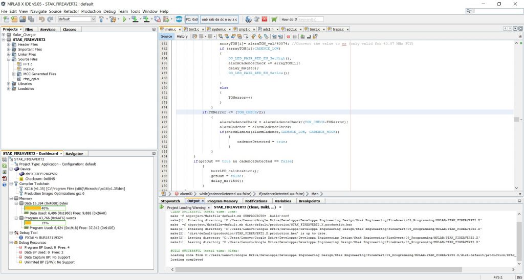
The programming environment is simply the software used to write the code and program/debug the microcontroller. In this case, we will use MPLAB X, Microchip’s software for the PIC family.
You will also need a compiler. A compiler is a program that converts the lines of code written in C to hexadecimal or binary so the microcontroller can understand it.
There are both free compilers, and paid compilers which perform optimizations so the code runs more efficiently and the output file is smaller.
For this tutorial, we will use Microchip’s XC16 compiler.
Creating a new project
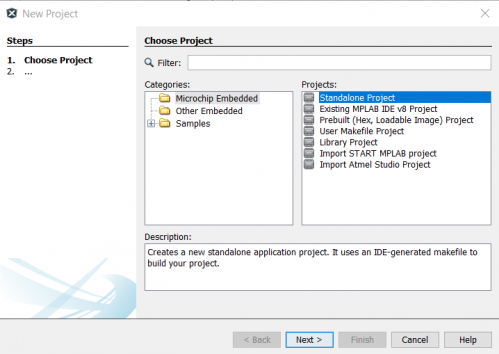
This is quite straightforward. Just click File>New Project, select Standalone Project, click next and follow the instructions. Just make sure you select the correct MCU, debugger tool (if any) and compiler.
MPLAB Code Configurator
MCC is a plugin created with the aim of making life simpler to new programmers. It makes the process of configuration and setting up the PIC quite easy as it can be done in a graphical way. The program then generates the code and imports it to your project.
It is worth saying that this plugin is not perfect, and sometimes you will have to fine tune and configure registers directly, however, it does most of the configuration without issue.
To check if you have MCC installed, go into Tools>Plugins and look for MPLAB Code Configurator. If it is installed and activated you should see this symbol on the toolbar above to open it:
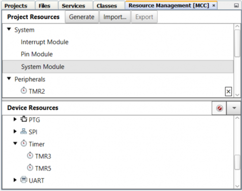
MCC is divided into modules. System Modules and Peripherals Modules.
System Modules control the clock frequency, programming pins, global interrupts and I/O pins. These modules are not optional and they need to be configured or the dsPIC33E will not work.
All the other peripheral modules can be activated and deactivated as required per the application.
System Module
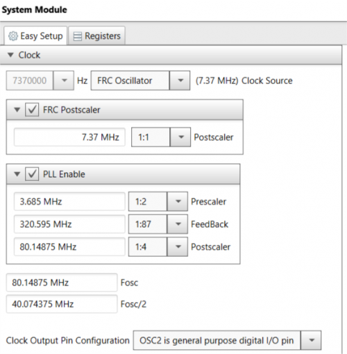
The first window that will appear when you open the MCC is the System Module. We will use this window to setup the clock frequency, programming pins and Watchdog timer.
- Select your clock source
- Use the postscaler and PLL to set the final frequency of the MCU clock. The value on Fosc/2 will be your final clock value.
- Click Enable Clock Switching. This is a safety feature in case the main clock source fails. I found out that if it’s not activated then the firmware won’t work.
- Select programming (ICD) pins group according to your schematic
Pin Module
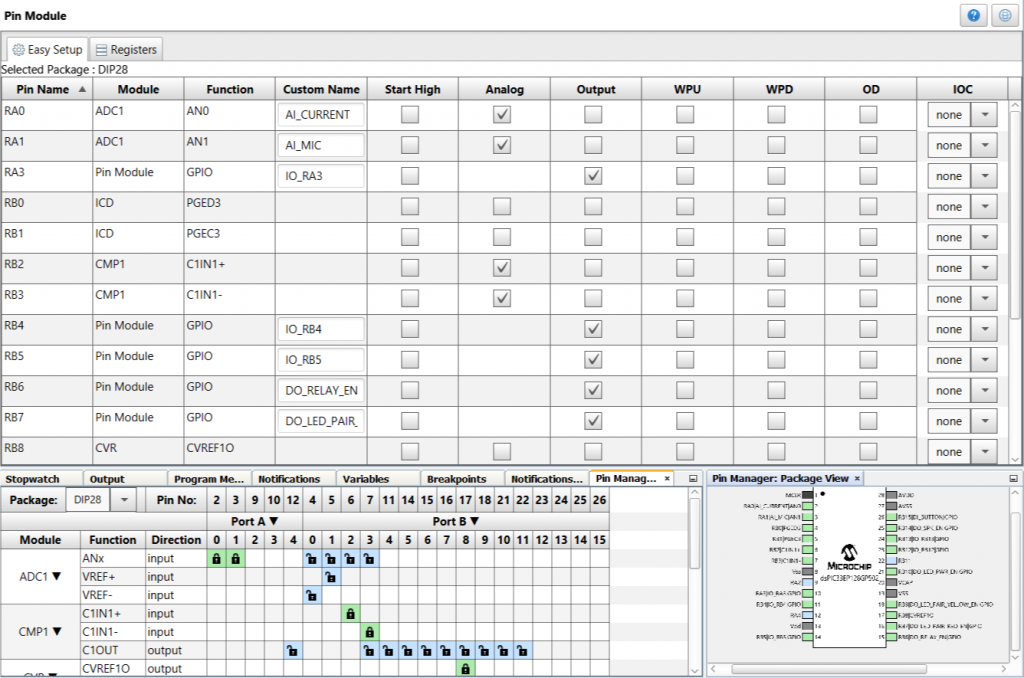
The pin module is a very versatile way to assign functions to every pin.
There is also a window that allows you to see where in the MCU physical package is your pin located, if it’s available, and to what it is assigned.
Use this window to set where your I/O pins are and declare if they are inputs, outputs or analogue. It is also good to add a name that tells you what that signal is. You can also add a pull-up/down by checking WPU/WPD.
Unused I/O pins
It is normal to leave some pins unused in your design. When this is the case, configure them as outputs and driving to low (default setting)
Timer Module
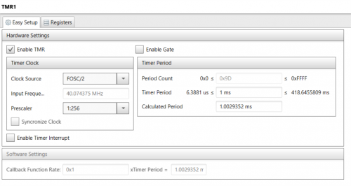
Double click on TMR1 on the Device Resources window to add this module to your configuration.
By modifying the clock source and Prescaler, the timer can count longer or shorter.
If you need a timer that counts up to 5ms, then choose a Prescaler value that has more than 5ms as max timer period as seen in the module configuration.
Then, type 5ms on the timer period option and the MCC will automatically set the register to the correct value of 5ms.
ADC Module
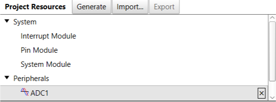
Double click on ADC1 on the Device Resources window to add this module to your configuration.
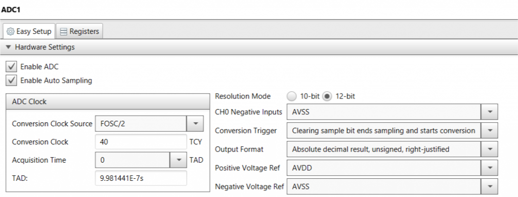
Select the ADC conversion clock by specifying a value in TCY. This is the time the ADC takes to make one conversion. If the value you select is too low, MCC will give you a warning. Just make sure the value is bigger than the warning value.
Also, for ease of implementation and to make the sample code shown later work, select Auto Sampling and the same Conversion Trigger as in the image.
Programming the MCU
After configuring the system modules and peripherals modules, click on Generate to create all the configuration files.
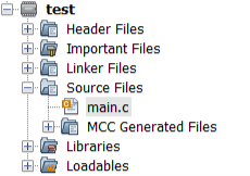
Then, go into the Projects (just above Project Resources) and open the Source Files folder tree to reveal the main.c file. This is where you will write your application code.
Once you have completed your code, click on the Clean and Build icon (broom and hammer) to verify that the compiler can compile your code (you will probably get errors if it’s your first time).
Fortunately the compiler tells you where the error is and sometimes how to fix it, check the Build window that appears when you click Clean and Build.
Once your code is built, you can click Make and Program Device (icon next to play) to upload the code into the MCU.
When doing this, make sure your PICKit4 is connected to the device, computer and the device has power.
Debugging
One of the main advantages of using a PIC and MPLABX compared to the Arduino and Arduino IDE, is that you have access to debugging tools.
In the Arduino, when you want to see how a variable changes, you normally have to use the serial monitor to display the variable at a particular part of the code.
You cannot stop the code, do a step by step execution and there is no way to know how long a code execution has taken.
All these mentioned features are very useful when you have to determine why your program doesn’t work.
To initiate the debugging. Have your Hardware connected as previously with the PICKit4 and click the debugging button (the one to the far right with the small play symbol).
Stepping through your code
Once the MCU has been programmed in debug mode, the following buttons will become available:
You can use the play/pause buttons to start/stop code execution and the reset to start the code from the beginning. The stop button will terminate the debugging session.
The other buttons are to step through the code.
- Step Over: step over a subroutine and go to the next line of code
- Step Into: go inside a subroutine and go to the next line of code
- Step Out: go out of a subroutine and go to the next line of code
- Run to cursor: run the program to where you have left the cursor
Another way to control program flow is by setting breakpoints. Breakpoints will automatically pause the program when they are reached.
To set up a breakpoint, click on the line where the line number appears. A small red box should be visible.
Watching variables
To add a variable to the watch window, simply right click on the variable and click New Watch. Your variable window will update every time you pause your program flow and show you the variables that have changed in red.
By default, it will show you the value of the variable in hex. To change this, simply right click on the value and select show in decimal.
Stopwatch
The stopwatch is very useful to determine how long it has taken to execute a segment of the code.
For example, if you want to check that your delay_ms subroutine is working, you can time how long it takes since the subroutine started until it ended. The stopwatch shows the timing in clock cycles:
To convert from cycles to time, simply divide the cycles by the clock frequency. For example for a cycle count of 210471196, the time that it took to perform all those cycles on a 40MHz system clock was 210471196/40000000 = 5.26secs.
Code Examples
Below are a few simple examples to help you get started:
Digital I/O’s read/write
MPLAB Code Configurator automatically creates some subroutines to read/write to I/O pins.
Assuming you have a pin set as an output with the name RELAY you would use:
RELAY_SetLow(); //Set the pin to 0V or logic low
RELAY_SetHigh(); //Set the pin to Vdd or logic high
bool readButton(void) //Read state of external button
{
bool buttonState = 0;
buttonState = BUTTON_GetValue();
return buttonState
}
Delay subroutine
The following subroutine creates a delay in milliseconds using TMR1. This code assumes that you have configured TMR1 to overflow at 1ms.
void delay_ms(int delay)
{
int i=0;
bool statusTimer1=0;
TMR1_Stop();
for(i=0; i<delay; i++)
{
TMR1_Start();
IFS0bits.T1IF = false; //Clear interrupt flag
while(statusTimer1 == false)
{
TMR1_Tasks_16BitOperation();
statusTimer1 = TMR1_GetElapsedThenClear();
}
TMR1_Stop();
statusTimer1 = 0;
}
}
Simple ADC read
This subroutine can be used for a single ADC reading. Assuming and ADC channel named as “ADC_pin” with the MCC pin module:
int readADC(void)
{
int ADCval = 0;
ADC1_ChannelSelectSet(ADC1_ADC_pin);
ADC1_SamplingStop();
while(!ADC1_IsConversionComplete()){}
ADCval = ADC1_Channel0ConversionResultGet();
return ADCval;
}
DSP Library: FFT of an audio signal
Here is a more complex subroutine that uses the DSP capabilities of the dsPIC33E.
Below is all the necessary code, including the variables you need to declare. For this code to work you need to include the dsp.h header file from the dsPIC33E DSP library and Twiddle factors for the FFT into your project. This is done by adding the file to the same folder tree as the main.c file.
Also, you need to configure the ADC to output results in signed fractional data type for this code to work.
#include ;
#define FFT_BLOCK_LENGTH 1024 //Number of frequency points in the FFT
#define LOG2_BLOCK_LENGTH 10 //Number of “Butterfly” Stages in FFT processing should be related to FFT_BLOCK as in 2^9=512
#define AUDIO_FS 44100//Sampling frequency of audio signal captured by the mic
int16_t peakFrequencyBin;
uint16_t ix_MicADCbuff;
uint16_t peakFrequency;
extern const fractcomplex twiddleFactors[FFT_BLOCK_LENGTH/2]__attribute__ ((space(auto_psv), aligned (FFT_BLOCK_LENGTH*2)));
fractcomplex sigCmpx[FFT_BLOCK_LENGTH] __attribute__ ((section (“.ydata, data, ymemory”), aligned (FFT_BLOCK_LENGTH * 2 *2)))={{0}};
void readMic(void)//Sample microphone input
{
ADC1_ChannelSelectSet(ADC1_AI_MIC);
ix_MicADCbuff=0;
for(ix_MicADCbuff=0;ix_MicADCbuff<FFT_BLOCK_LENGTH;ix_MicADCbuff++)
{
//Insert delay subroutine here
ADC1_SamplingStop();
while(!ADC1_IsConversionComplete()){}
sigCmpx[ix_MicADCbuff].real = ADC1_Channel0ConversionResultGet();
sigCmpx[ix_MicADCbuff].imag = 0;
}
}
void signalFreq(void)//Detect the dominant frequency of the audio picked by the microphone
{
readMic();
FFTComplexIP (LOG2_BLOCK_LENGTH, &sigCmpx[0], (fractcomplex *) __builtin_psvoffset(&twiddleFactors[0]), (int) __builtin_psvpage(&twiddleFactors[0]));// Perform FFT operation
BitReverseComplex (LOG2_BLOCK_LENGTH, &sigCmpx[0]);// Store output samples in bit-reversed order of their addresses
SquareMagnitudeCplx(FFT_BLOCK_LENGTH, &sigCmpx[0], &sigCmpx[0].real);//Compute the square magnitude of the complex FFT output array so we have a Real output vector
VectorMax(FFT_BLOCK_LENGTH/2, &sigCmpx[0].real, &peakFrequencyBin);//Find the frequency Bin ( = index into the SigCmpx[] array) that has the largest energy
peakFrequency = peakFrequencyBin*(AUDIO_FS/FFT_BLOCK_LENGTH); //Compute the frequency (in Hz) of the largest spectral component
}
Saving to Flash Memory
Normally, when power is removed from an embedded device, all data is lost except the one saved on the flash memory.
It is very useful to save data on flash memory so when the device is unpowered, these values can be restored later.
The following subroutine allows you to store up to 128 variables on the dsPIC33E flash memory.
You need to download the rtsp_api.h and rtsp_api.s libraries from Microchip and include them in your project for this subroutine to work.
#include “rtsp_api.h”
#define ROWLENGHT (128)
#define PAGE_MIRROR_LEN (128 * 8)
int16_t pageMirrorBuff[PAGE_MIRROR_LEN];
int16_t temp;
uint16_t variable1;
uint16_t variable2;
uint16_t variable3;
uint16_t nvmAdr, nvmAdru, nvmAdrPageAligned, nvmRow, nvmSize, nvmOffset;
int16_t iParameters[ROWLENGHT]__attribute__((space(prog), address(0x1000)));
void initRTSP(void)// Call this subroutine at initialization fo the device only once
{
nvmAdru = __builtin_tblpage( &iParameters[0] );
nvmAdr = __builtin_tbloffset( &iParameters[0] );
nvmAdrPageAligned = nvmAdr & 0xF800; // Get the Flash Page Aligned address
nvmRow = ( (nvmAdr >> 7) & 7 ); // Row in the page
nvmSize = ROWLENGHT;
nvmOffset = 8;
}
void readFlashPage(void)
{
temp = FlashPageRead( nvmAdru, nvmAdrPageAligned, pageMirrorBuff );
}
void updateRamBuffer(void)
{
iParameters[0] = variable1;
iParameters[1] = variable2;
iParameters[2] = variable3;
temp = FlashPageModify( nvmRow, nvmSize, iParameters, pageMirrorBuff );
}
void eraseRamBuffer(void)
{
iParameters[0] = 0;
iParameters[1] = 0;
iParameters[2] = 0;
temp = FlashPageModify( nvmRow, nvmSize, iParameters, pageMirrorBuff );
}
void eraseFlashPage(void)
{
temp = FlashPageErase( nvmAdru, nvmAdrPageAligned );
}
void rowFlashWrite(void)
{
int16_t i;
temp = FlashPageWrite( nvmAdru, nvmAdrPageAligned, pageMirrorBuff );
for( i = 0; i < (PAGE_MIRROR_LEN); i++ ) // Clear Page Mirror Buffer
{
pageMirrorBuff[i] = 0;
}
}
void programParameters(void)//Call this subroutine to write new values to flash memory
{
Final word
In this beginners guide, we have covered everything you need to get started with the dsPIC33E.
You have learnt the essential hardware connections and electronic components required for the MCU to work. You have also learnt how to use MPLAB Code Configurator to set the different settings and parameter of the dsPIC33E.
Finally, you have been shown how to program and debug the MCU and some basic subroutines to help you get started.
—–
This is a guest post by my engineer friend Roberto Weiser. Roberto is an electronics design engineer with experience in audio electronics and battery systems for electric vehicles. He currently works as a freelance engineer and is the founder and lead content writer at Developpa.io which focuses on electronics product development, sustainable design, and creating devices for the good of humanity. Roberto can be reached at info@developpa.io.
—–




Can they compete with C2000 series?
Hi I also just read your article, is some of the code missing at the end for the Write subroutine – void programParameters(void)//Call this subroutine to write new values to flash memory
{
here
If so could you add it.
Thanks,
Mark
Hi,
I just read your article and it is really helpful.
However, I have no idea about what configurations should I choose, such as the clock values.
I am using dsPIC33EP64GS502, 28 pin version,
can you help me out?