
The SIM800 Cellular Module and Arduino: A Powerful IoT Combo
The SIM800 from SimCom and the Arduino UNO are two of the most popular development modules to get you started with IoT. This article discusses how to connect physical objects and the digital world in new and creative ways.

The Internet of Things (IoT) has been a trending field in the world of technology. From consumer electronics to business and industrial processes, IoT has changed the way we work.
The SIM800 from SimCom and the Arduino UNO are very popular due to their support from the hobbyist and developer community.
The SIM800 is a cellular communication module that can make calls, send email and SMS texts, and even connect to the internet.
The module is intended to operate like a mobile phone, but it needs external peripherals to function properly. The SIM800 can do a lot of things but in this article we will focus on the internet capabilities of the module.
Adding the SIM800 module with an Arduino will enable you to develop countless innovative projects. Your imagination is the limit.
The SIM800 module is not only great for maker projects, but it can also be an affordable and viable option for use as a cellular communication module in a production product.
Considerations
Let’s start by reviewing the pros and cons of the SIM800 so you can decide if this module is the right solution for your project.
Pros
- Easy to develop and a popular choice among both hobbyists and product developers
- Extensive features including voice calls, SMS, and internet access
- Small size is ideal for portable products and wearable tech
- Very affordable module from a Chinese manufacturer
- The manufacturer of the SIM800, SimCom, also offers numerous other communication modules including the SIM868 which includes built-in GPS functionality.
Cons
- Older 2G technology with limited data speeds (GSM/GPRS). GSM is also being phased out in most regions.
- Not necessarily the smallest, lowest power or highest performance cellular module available. Nonetheless the SIM800 is a great general purpose cellular module.
WARNING: The SIM800 is an older GSM cellular module, and unfortunately most regions of the world are actively phasing out GSM cellular networks, so it is not recommended for new designs.
Programming & Prototyping
Basic Connections
The connections for a basic serial communication setup between an Arduino and the SIM800 are quite simple. All you need is three lines between the SIM800 and the Arduino. This includes ground plus UART send and receive lines.
You need to have the following hardware components and installed software on your PC as listed below.
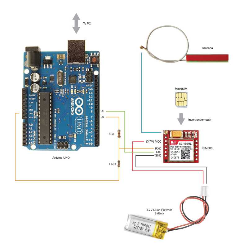
Figure 1: SIM800 and Arduino UNO basic connections.
Components
- SIM800L breakout board
- Arduino UNO board or similar
- MicroSIM Card
- USB cable (Arduino to computer)
- 3.7V Lithium Polymer Battery (Supply for SIM800L)
Software
- Arduino IDE (Installed to your PC)
References
Pin connections:
| SIM800 | Arduino UNO |
| GND | GND |
| SIM_TXD | D8 |
| SIM_RXD | D7 |
Now, insert the microSIM card into the back of the SIM800 module. Then, connect the SIM800 TX and RX to the Arduino D8 and D7 respectively. These are the serial UART connections which allow communication between the two modules.
Keep in mind that the send pin on the SIM800 connects to the receive pin on the Arduino, and the receive pin on the SIM800 connects to the send pin on the Arduino.
Note that the Arduino Uno uses 5V GPIO whereas the SIM800 uses 3.3V level logic and is not 5V tolerant. This means the TX signal (D7) coming from the Arduino Uno must be stepped down to 3.3V so as not to damage the SIM800. There are several ways to do this but the easiest is to use a simple resistor divider (1.69k for the top resistor, and 3.3k for the bottom resistor is a good choice).
Next, connect the antenna to the mini socket located in the upper left area of the module.
Power Supply for SIM800
The SIM800 needs to be powered by 3.7V which is a common standard among most cellular modules. One might think of using the Arduino’s 5V and 3.3V supply from the Arduino but this is not advisable.
The SIM800 is specified to use a power supply in the range of 3.4V to 4.3V. So, using 5V could damage the SIM800 module and 3.3V is not enough to reliably power it.
Therefore, an external 3.7V Li-ion Polymer battery is used as the power source for the module.
Ideally, a power decoupling circuit is added to the input supply. We will discuss this circuit in more detail in the next sections.
Serial Monitor
The serial monitor is your interface with the Arduino and it communicates with your SIM800 as well. You can use the serial monitor to check the current status of the device. Also, you can send commands through the serial monitor to communicate with the Arduino.
Simple Serial Communication
The code below will enable the Arduino to communicate with the SIM800. Initially, we set up the pins and initialize a serial communication link between the two devices. Then, we set the baud rate to 9600.
In the looping part of the code, the SIM800 will continuously wait for any inputs from the serial monitor and send it to the SIM800 through the D7 pin (RX for SIM800). It will also continuously read the D8 pin (TX for SIM800) if the SIM800 has any responses.
| #include <SoftwareSerial.h>//SIM800 TX is connected to Arduino D8
#define SIM800_TX_PIN 8 //SIM800 RX is connected to Arduino D7 #define SIM800_RX_PIN 7 //Create software serial object to communicate with SIM800 SoftwareSerial serialSIM800(SIM800_TX_PIN,SIM800_RX_PIN); void setup() { //Begin serial communication with Arduino and Arduino IDE (Serial Monitor) Serial.begin(9600); while(!Serial); //Being serial communication with Arduino and SIM800 serialSIM800.begin(9600); delay(1000); Serial.println(“Setup Complete!”); } void loop() { //Read SIM800 output (if available) and print it in Arduino IDE Serial Monitor if(serialSIM800.available()){ Serial.write(serialSIM800.read()); } //Read Arduino IDE Serial Monitor inputs (if available) and send them to SIM800 if(Serial.available()){ serialSIM800.write(Serial.read()); } } |
Once your setup is complete, and your Arduino is connected to your PC, compile the code above and upload it to the Arduino.
Now that we have established a basic connection let’s try to communicate with the SIM800 module by sending AT commands through the serial monitor.
AT commands are short command keys used to execute the desired functions on the SIM800. We send these codes through the Arduino and it will relay the commands to the SIM800 for execution.
The most basic AT command you can use is “AT”. When you type or request this command in the serial monitor the response will be “AT” as well. This response verifies that the Arduino is communicating properly with the SIM800.
AT //Serial communication established
Take note that other commands will have different responses based on your requests.
Downloading a Simple Web Page from the Internet
It is fascinating to see how the SIM800 module can download a web page. You can do this by executing a series of AT commands through the serial monitor.
One thing to do first is to check for signal quality. There are times that we may not be able to connect to a network internet. What we need to do is to check for signal quality. Use the “AT+CSQ” command to check the cellular signal level.
This is not a prerequisite for establishing a connection to the internet but it will be helpful when monitoring the signal level during debugging.
In this walk through, we will request a web page that contains weather forecast information in JSON format from the Weather Underground website.
Let’s first check the signal quality by typing “AT + CSQ” to verify.
AT+CSQ //Check for signal
Next, let’s set the device to full functionality mode. This is already the default mode but just to make sure, we will explicitly define it.
AT+CFUN=1 //Full functionality mode
Next, we connect to a data network.
AT+CGATT=1 //Attach to a GPRS network
The next commands are important settings for connecting to your network properly. Verify the correct APN for your data network. I am using SMART as my network and ‘internet’ is its APN.
AT+SAPBR=3,1,"CONTYPE","GPRS" //Configure bearer profile 1

AT+SAPBR=3,1,"APN","internet" //"internet" is APN for Smart

AT+SAPBR=1,1 //To open a GPRS context
Next, let’s establish a web session by setting up a browser-like environment for the SIM800. First we initialize and set the HTTP settings.
AT+HTTPINIT //Init HTTP service

AT+HTTPPARA="CID",1 //Set parameters for HTTP session

AT+HTTPPARA="REDIR",1 //Auto redirect
Then input the website URL you wish to download.
AT+HTTPPARA="URL","http://api.wunderground.com/api/f2225df15bd32114/forecast10day/q/autoip.json"
The next command tells the SIM800 to start downloading the web page.
AT+HTTPACTION=0 //Get session start
Once the page has completely downloaded, you may view the whole content of the web page through the serial monitor.
AT+HTTPREAD //Read the data of the HTTP server
Below is the list of the most common AT commands for the SIM800. There are even more AT commands available, but this list will get you started with defining settings and connecting to a network internet.
| AT command | What it does | |
| SIM800 routine | AT | Check interface |
| AT+CPIN? | Check if SIM is unlocked | |
| Initialize phone | AT+CREG? | Check network status |
| AT+CFUN=0 | Minimal phone functionality (Sim Reset) | |
| AT+CFUN=1 | Full functionality | |
| AT+CSQ | Check signal | |
| GPRS Setup | AT+CGATT? | Check if connected to GPRS |
| AT+CGATT=0 | Detach from GPRS network | |
| AT+CGATT=1 | Attach to GPRS network | |
| AT+CIPSHUT | Reset IP session | |
| AT+CIPSTATUS | Check if IP stack is initialized | |
| AT+CIPMUX=0 | Setting up single connection mode | |
| Ping Tests | AT+CSTT=”internet” | Ping request |
| AT+CIICR | Bring up wireless connection | |
| AT+CIFSR | Get local IP address | |
| AT+CIPSTART=”TCP”,”url” | Start connection | |
| AT+CIPSEND | Request initiation for data sending | |
| Bearer Configure | AT+SAPBR=3,1,”CONTYPE”,”GPRS” | Configure bearer profile 1 |
| AT+SAPBR=3,1,”APN”,”internet” | Set “internet” as APN. Varies per different network | |
| AT+SAPBR=1,1 | To open a GPRS context | |
| AT+SAPBR=2,1 | To query the GPRS context | |
| AT+SAPBR=0,1 | To close GPRS context | |
| Get Location | AT+CLBS=? | Base station test command |
| AT+CLBSCFG=0,1 | Get customer ID | |
| AT+CLBSCFG=0,2 | Get Times have use positioning command | |
| AT+CLBS=1,1 | Get current longitude, latitude and precision | |
| AT+CLBS=3,1 | Get access times | |
| AT+CLBS=4,1 | Get current longitude, latitude, precision and date time | |
| Network Time Synchronize | AT+CNTPCID=1 | Set NTP use bear profile 1 |
| AT+CNTP=”time.upd.edu.ph”,32 | Set NTP service URL and local time zone | |
| AT+CNTP | Start sync network time | |
| AT+CCLK? | Query local time | |
| HTTP Request | AT+HTTPINIT | Initialize HTTP service |
| AT+HTTPPARA=”CID”,1 | Set parameters for HTTP session | |
| AT+HTTPPARA=”REDIR”,1 | Set to enable redirect | |
| AT+HTTPPARA=”URL”,”http://m.smart.com.ph” | Set the URL | |
| AT+HTTPACTION=0 | Start the HTTP session | |
| AT+HTTPREAD | Read the data of the HTTP server | |
| AT+HTTPTERM | Terminate HTTP service | |
| AT+HTTPSTATUS? | Check HTTP status |
What else can you do with the SIM800?
The SIM800 can be embedded into hand-held or miniature products such as wearables. Also, you can build a simple home automation system, a remote wireless sensor or a GPS tracker using the SIM800 and an Arduino.
Sample Project: Low-cost Weather Forecast for Farmers
One of the projects I’ve created is a low-cost, weather forecasting device using the SIM800 and a Gizduino (an Arduino clone). The project provides a 10-day weather forecast represented through colors.
The device locates the user and downloads weather data from Weather Underground, a popular weather forecasting service. Here’s the link to the full case-study.
One of the SIM800 features used in this project is the ability to identify the location of the device. A rough estimate of location was sufficient for this project, even though it is not nearly as accurate as GPS.
The acquired location is used as the reference location for the weather data being requested. For such an application there really is no need for the accuracy provided by GPS, and cellular triangulation provides more than sufficient accuracy. The series of commands are listed below:
AT+CLBSCFG=0,2 //Get Times have use positioning command

AT+CLBS=1,1 //Get current longitude, latitude and precision

AT+CLBS=3,1 //Get access times

AT+CLBS=4,1 //Get longitude, latitude, precision and date time
SIM800 Schematic and PCB Layout Considerations
If you wish to embed the SIM800 module into your product, you should keep the following considerations in mind.
The SIM800 datasheet suggests adding a power decoupling circuit to the input supply of the SIM800 module. This will provide a stable power supply and prevent surges that may damage the SIM800 module.
Three capacitors (100uF, 33pF, and 10pF) and a Zener diode connected in parallel with the supply make up the decoupling circuit.
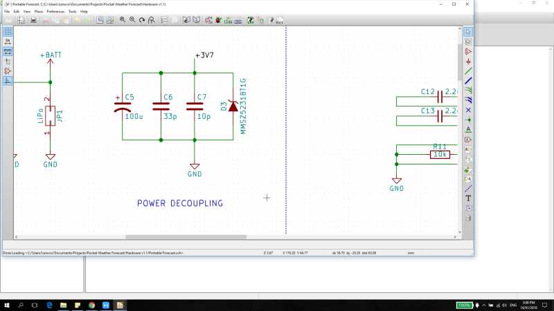
Figure 2: Power decoupling circuit for SIM800 3.7V supply
GSM Antenna
There are two ways you can add an antenna to your product or device when using the SIM800. You can use a mini RF coax connector (recommended) or an SMA connector.
The RF interface has an impedance of 50 ohms. The trace impedance with the antenna should also match this impedance with 50 ohms as well.
Designing RF traces for the SIM800 antenna is critical and complex. You may want to ask for guidance from an RF expert since antenna traces are one of the most common mistakes made on PCB layouts.
To avoid any unnecessary FCC certification complications you should closely follow the manufacturer’s layout guidelines.
Summary
The SIM800 is an excellent choice for providing 2G cellular functionality to both maker projects and production products. It’s small size, low-cost, and ability to communicate via a simple UART interface using AT commands makes it an excellent choice for many applications.
The SIM800 is also a very popular module with a large support community of makers and product developers than can help you work through any technical issues. They are broadly available from numerous suppliers and a variety of development kits based on the SIM800 exist to help you get started.
This article was contributed by Joseph Ricafort. Joseph is a Test Engineer who builds electronics projects in his spare time. He wants to build small projects that provide big impacts to those in need. His weather forecasting project for farmers was selected as the winning project for a recent Predictable Designs contest.

Hi
Where should I find the header file ‘SoftwareSerial.h’
Hi,
I am using the SIM800L V2.0 5V module for my project.
the issue I am facing now is a Network issue.
previously I am facing a continuous restart problem, this problem was solved by adding a 1000Mfd capacitor in the GSM module power pin.
After that, the problem is Network is not detected
kindly looking for your help to solve this issue
Hello… I am Aksher Maxvel from Chennai India. I am trying a development with SIM800L. All voltage, ampere, connections are ensured.
The problem is the network is not getting registered. I am using Airtel SIM card and I have also tried with different SIM cards..
Can you please help me to solve this issue
Same problem for me
I am also in Tamilnadu
I tried Airtel and Vodafone SIM cards no improvements
Hi,
Can we connect SIM800 using websocket protocol, websocket is basically extended virsion of HTTP, is this possible with SIM800?
There’s one thing I always wish these project would include is how to send the AT commands through the arduino code to the gsm modules and how to attach certain parameters that is needed for certain AT commands to be executed.
Hi,
thanks for the well written article. As you mentioned in the beginning that the SIM800L module is not the most power efficient module available I wonder whether you could recommend a module that is able to send and receive SMS but uses less power than the SIM800L. Thanks in advance.
Hi sir. I tried sim 800l module interfacing to arduino uno and i connected as pre refereed circuit diagram but i connected DC-DC buck converter also in sim 800l module the signal was not defecting even buck-converter also connected and sim is also working please give replay.
Hello sir,I am interced GSM Sim800L module with aurdino and powers are connected with buck but i didn’t get any signal from GSM module and also tried to Diode also but same problem. What i can do ?
http://bigbelectronics.in/product.php?product=sim800l-gprs-gsm-module-microsim-card-core-boardquad-band-ttl-serial-port-pcbantenna
I tried sim 800l module interfacing to arduino uno and i connected as per refereed circuit diagram but i connected DC-DC buck converter also in sim 800l module the signal was not defecting even buck-converter also connected what is the problem i dont know could any one know please give reply.
hi sir i interfaced Neo 6M GPS U-blox NEO-6M GPS Module with node mcu and i get the data from gps module using local wifi but i cant get the latitude, longitude data in bike ride i don’t know what the reason please tell any solution
Hello sir,
I baught a SIM 800L and Arduino UNO R3. But I can not run SIM 800L. Would you please help me?
Actually I want to make a little project. Like on/off a relay by sending SMS or DTMF system. Please help me. Thanks
Hi, Awesome post!
Quick question !
Is there a way to use sim808 to connect to AWS IOT?
or simply as sim808 dosen’t support TLS 1.2 but supports tls 1.0 (I think). can we write code to connect to AWS IOT using sim808 in Arduino?
What processing (CPU),space(flash) and ram requirements are required to implement tls 1.2 on Arduino using sim808?
Hi Ahmad,
Did you find any solution to this? I am trying to connect SIM800L to GCP IoT Core and it supports only TLS1.2 too.
Hi did you find a way to this ! i have the same issue
In theory you can do that with SSL library like BearSSL or AXTLS. However, the communication between your MCU and the GPRS is UART, an async communication is exposed to noise and bit loss in the way and there is no way to reply loss packet because there is no acknowledge mechanism between you and the GPRS
Hi, same problem with Bot Telegram. If I understood , it use tls 1.2.
Looking for some solution, I saw the SIM800 application note v1.05. It says that now sim800 supports also tls1.2
My sim800l is R14.18 version. I can’t understand what to do to enable TLS1.2.
Do I need to update SIM800 firmare version or just to get some SSL certificate by means of AT commands.
Any suggestions?
Nice work
Hi,
So basically what i want is a system where i simply use a gsm module like sim800l module and whenever there is a trigger i want the module to send an email to a particular person now there are 2 ways in which this can be done :
– First is that i use the inbuilt functionality of the gsm module to access my gmail account and then send an email through it ( which btw i tried a lot but didn’t worked for me )
– Second is that i use some sort of an api or something (IFTTT maybe) which can get an HTTP GET or HTTP POST command and in return, it sends an email to a person.
Solutions for both methods are welcome. Please help its urgent.
Getting started with this module.
Looks like the logic level resistors are the wrong way round in the picture of the wiring but correct in the text.
I made the connections as specified in the article, loaded the code but the gsm does not respond to any commands, It turns on with the power LED on and the network LED flashing every 3-4 seconds. I dont know what the problem might be
Sir, I am in Kerala, India. I am very impressed with your article and have accomplished setting up one. Works fine.
Thank You Very Much.
You are most welcome. Thanks for the comment.
Johm
Thank you for that useful information, I am trying my first project with SIMXXXX modules and its like I going with sim800l because I have Got some light about it
Great info! The quality of this article stands out compared to others that deal with the SIM800 and Arduino. Thank you.
I’ve got a question regarding the power decoupling circuit you mention and the three capacitors (100uF, 33pF, and 10pF) and Zener diode, that are involved:
Does this only apply to cases where you want to connect to the SIM800 module directly, without the breakout board that it usually comes on?
In Figure 1 of this article the breakout board has some additional components like a 470uF capacitor (big yellow block). I assume if you use the breakout board, all you have to do is connect a power supply and not worry about bypass capacitors and the Zener diode. Is this correct?
Thanks Daniel for the comment. You are correct and those decoupling caps are already on the breakout board.
John
I just discovered your site and I’m loving it. Thanks for your efforts. I seem to have underestimated SIM800, Now I don’t regret buying a couple of its modules.
Thank you Moabi!
Unfortunately, here in the EU, 2G is going to shut down on 2025 and 3G in 2020 (yes, 3G is going to shut down earlier than 2G). This means that, for designing a product that connects to cellular networks for being sold here, we’ll have to use 4G or 5G modules! That’s crazy! And if 3G modules are expensive, 4G and 5G will be even more expensive!
Yes, this is a major headache for all kinds of IoT products that don’t require high bandwidth. In the U.S. at least 3G is supposed to be around for while. As you point out 3G solutions (and especially 4G) are so much more expensive than 2G. Yes, I agree, crazy!
John
Hi, Thanks for great article. I had a dream of making fleet management project using SIM800. Sadly, more countries, including I am currently residing, stop supporting 2G network. I have to give up my Idea. The module such as SIM 5320 which supports 3G is way too expensive. I would love to see if you have any idea for similar low cost IoT solution with 3G.
Thank you for the comment! Yes, any 3G module is going to be significant more expensive than a 2G solution. The prices for SimComm modules (such as the SIM800 and SIM5320) are usually hard to beat. The other 3G module I like is the Telit HE910. You might also check out the SARA-N2 or LISA-N2 3G modules from ublox. However, I’ve found solutions from Telit or uBlox to be considerably higher than SimCom solutions. Best wishes, John.
Hi John
I noticed you are using the sim800l module, according to the datasheet, it is recommended to use a max of 3.1v io level. The arduino uno runs at 5v 16mhz, therefore tx and rx high levels would also be 5v.
Im not questioning, im merely looking for confirmation that the sim800l can handle that levels reliably over time. Im designing a product based on this module and incorporated level shifting only for tx from uC to sim800l. Any feedback would be highly appreciated. And thanks, i really enjoy reading your articles
Hi Christo,
Thank you for your comment. Yes, you are absolutely right! This was a guest post and I missed this mistake during my review. You’ve done the right thing and a level shifter is only needed on the TX line from the microcontroller to the SIM800 to step it down. No level shifter is needed on the other line because the 3.3V level from the SIM800 is high enough for the microcontroller to detect it as a high.
I’ll get the article fixed asap.
Thanks again and good catch!
John
Hi John,
Great article there. I think the sim800 module has been heavily underestimated, sim800 gives us the ability to build low cost and even powerful IoT applications.
If you build the SIM800 with an eSIM (embedded SIM), you can build IoT devices that can be deployed to virtually anywhere in the world (expect countries like Australia). I recently released an Arduino Library for the SIM800 focused solely on building low-end IoT devices called BareBoneSim800 – https://github.com/thehapyone/BareBoneSim800.
Thanks for this great comment and feedback! Thanks for sharing the Arduino library for the SIM800 that you released.
Best wishes,
John
Hi Ayo,
I would like to ask regarding what you had quoted:
” If you build the SIM800 with an eSIM (embedded SIM), you can build IoT devices that can be deployed to virtually anywhere in the world (expect countries like Australia). ”
can I ask why is that?? 😀
(and if John Teel would be able to see this, do you know why Australia is an exception implementing SIM800? Cheers :))
Thanks,
Mheru
Hi Mheru,
Australia is an exemption because they have stopped a nationwide usage of 2G networks, but the SIM800 is based only on 2G network and one of the main reason why it is that cheap too.
Most telcos are stopping (probably stopped) their 2G networks and are focusing on 3G upwards.
Regards,
Ayo