
From Arduino Prototype to Mass Production
In this in-depth guide you will discover how to build an Arduino prototype, the pros and cons of using an Arduino in a commercial product, and how to design your own custom PCB that can be mass manufactured.
In this in-depth guide you will first learn how to build a prototype of your product using an Arduino.
Then we will look at whether or not using an Arduino in a commercial product is allowed, and if so whether it is practical for production.
Finally, you’ll learn how to develop your own custom “Arduino” board for better use in mass production.
How to Build an Arduino Prototype
Creating a prototype based on an Arduino is an excellent start to bringing a new electronic hardware product to market.
An Arduino, or more specifically an Arduino architecture, can be successfully used in some embedded designs. This can provide a less technically complex path to market for many makers.
However, the proliferation of Arduino and Arduino-compatible boards, each with its own name, can lead to confusion over what Arduino is, and which version you should choose for your particular project.
With names such as Uno, Leonardo, Mega, Nano, Zero, Due and more, simply listing their specifications is not enough information to decide which you should choose for your given application.
Let’s take an integrated approach to understanding what makes an Arduino an Arduino in the first place.
Arduino can be viewed from many angles. First, there is the hardware (HW). There are many versions of Arduino compatible hardware, and the only things that are common among them is they all have a microcontroller and a USB port.
Then there is the firmware. In this area, first, there is the bootloader that allows the user to download the application code to run on the hardware. Then, there is the Arduino core. This core is actually not pre-loaded into the microcontroller. It is compiled, and linked along with the user application code, and then loaded.
This core is what makes Arduinos based on different microcontrollers behave in the same way. A person familiar with writing code on one Arduino platform can easily migrate to a different board.
Adding to the ease of transitioning to different hardware is the Integrated Development Environment, or IDE, which behaves in the same way regardless of the chosen hardware.
Finally, there is a huge library base. This, and the ever increasing capabilities of Arduino compatible modules, is what makes Arduino so ubiquitous in embedded applications of moderate complexity.
Arduino hardware
Arduinos originally had Atmel – now part of Microchip – AVR ATMega8 microcontrollers. This is an 8-bit microcontroller with 8 KB of flash and 1KB of SRAM. Still, as in most microcontrollers, it has an integrated USART, several timers, ADC’s, SPI, digital IO’s that can also be programmed as PWM and external interrupt inputs.
On the board, a UART to USB interface chip was added to allow communications with an external PC, and the available pins of the microcontroller were made available to the user.
The board was open-source, and the HW schematic was made available. This, in turn, gave rise to third-party daughter boards – called Shields – that augmented the capability of the Arduino board. Examples of these shields include Ethernet, Wi-Fi, GPS, ZigBee, Sound, and more.
While there were many iterations of this line that included higher-end versions of the Mega8 such as the Mega168, or the Mega328, with 32K of flash and 2K of SRAM, they were all still based on 8-bit microcontrollers running at relatively low clock speeds, with relatively small amounts of memories.
When ARM Cortex M series of 32-bit microcontrollers became price-competitive with AVR Mega’s, several vendors started making Arduino boards based on the ARM microcontrollers.
Since this was a complete departure in the base HW of the original Arduino, the definition of what constitutes an Arduino board should be widened.
So, here are some of the attributes that all Arduino boards share, regardless of the underlying solution:
1) It can run Arduino code. This means it has a GCC, or similar, C++ compiler, which is the compiler behind Arduino.
2) It has an Arduino core that provides a basic set of software functionalities such as digital IO, serial communication, I2C, PWM and timers.
3) It also has an Arduino compatible bootloader.
4) It has a USB interface to allow connection to a PC, including Macs, Linux machines and others.
5) User code can be downloaded to be run on the board directly from the Arduino IDE. This means it has a board HW definition in the Arduino IDE. In turn, it means that the Arduino IDE has information about the clock frequency, memory layout, IO port mapping, and other details about the underlying microcontroller used in the board.
Currently, there are many such compatible boards. Some are based on Atmel’s SAM family of ARM microcontrollers. These include the Arduino Due and the Zero.
Adafruit and SparkFun also have Arduinos such as the Feather M0. ST Microelectronics also has a range of evaluation boards, like the Nucleo series, that are Arduino compatible.
There is also a very inexpensive board, commonly known as STMduino or Blue Pill, that is already Arduino compatible, or can be made Arduino compatible. It is based on an STM32F103C8T6, an ARM Cortex M3 microcontroller.
Finally, the ESP32, based on the high-performance Tensilica Xtensa microcontroller core, is also Arduino compatible.
Arduino core
Writing code in Arduino is almost like writing code in C/C++, except for being somewhat simpler. This is because the Arduino programming “language” is actually C++, with some simplifications targeted specifically for embedded applications that run on compatible HW.
Consider the simple test.ino example below:
void setup() {
pinMode(LED_BUILTIN, OUTPUT); // Initialize digital pin LED_BUILTIN as an output
Serial.begin(9600); // Set serial port to 9600 baud
}
// Repeat forever
void loop() {
Serial.println(“ON”);
digitalWrite(LED_BUILTIN, HIGH); // Turn the LED on
delay(1000); // Wait for a second
Serial.println(“OFF”);
digitalWrite(LED_BUILTIN, LOW); // Turn the LED off
delay(1000); // Wait for a second
}
If this were written for, say, an ATMega8, using Atmel’s AVR Studio IDE, this would have required at least fifty, or more, lines to write. Several header files would have to be included. LED_BUILTIN would have to be defined as a pin on a particular port.
The user would have had to write setup functions to initialize, and access, the IO ports and the USART. This would have required many lines to set up the appropriate microcontroller registers.
This code would also have been different for different microcontrollers. Here, the Arduino core provided a Hardware Abstraction Layer (HAL) that made pinMode or Serial.begin work the same way regardless of the underlying hardware. In the above example, the Arduino core took care of all this.
How, for example, Serial.println is implemented, is now transparent to the user. All that has to be done is to select the right board, and it just works, regardless of whether the board is AVR or ARM based.
Bootloader
A bootloader is a small piece of code that is preloaded into the microcontroller, and is executed upon reset. It then tries to communicate with the PC. If this is successful, and the correct handshake is established, the PC then downloads the application code to the microcontroller.
The bootloader then flashes the microcontroller’s application flash memory, and transfers control to this application code.
If there was no handshake from the PC, then, after a timeout period, the bootloader automatically transfers control to the application code section to begin executing the application.
Of course, if there is no valid application that had been previously loaded, the microcontroller does nothing. All Arduino boards have this bootloader pre-installed in the bootloader section of their microcontroller.
Remember that the bootloader cannot boot load itself. Some other means must be used to upload this bootloader code into the microcontroller.
All Arduinos have some power-on delay before executing the application code due to the bootloader needing to wait for new application code, if any, to be bootloaded.
Also, if a microcontroller does not have the ability to flash itself, then it cannot have a bootloader.
Arduino IDE
There are many IDE’s that are compatible with Arduino, such as PlatformIO and Visual Micro. The Arduino IDE is still the most popular, and is the one discussed in this article.
This IDE is not the most sophisticated for writing and debugging code, and it cannot be used to develop modular code. However, it does support all of the features of the Arduino development ecosystem.
In the Arduino Hardware section, it was mentioned that the Arduino IDE can support many different boards that are built around different microcontrollers.
In order to add support for a given board, just go to Tools > Board > Board Manager… as shown in Figure 1 below. A pop-up like the one in Figure 2 will appear. Just scroll down, and choose the board to install.
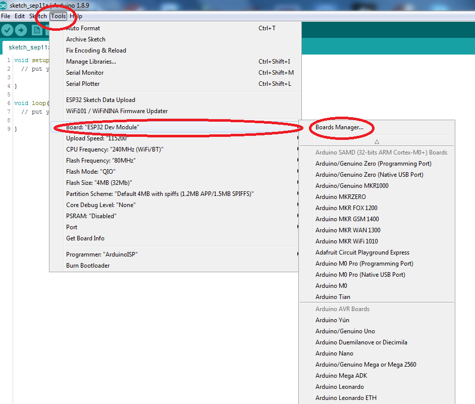 Figure 1 – Getting to the Arduino Board Manager
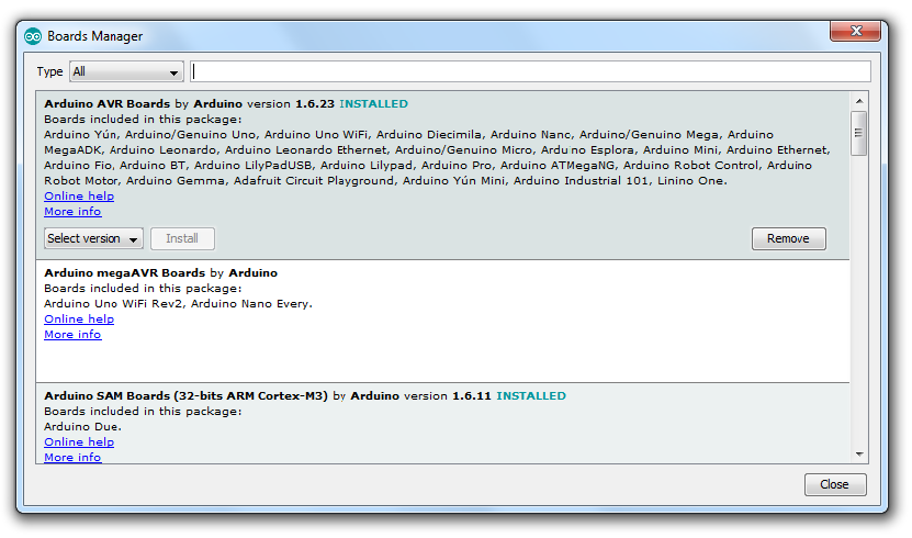 Figure 2 – Board selection in Arduino
Sometimes, however, a board is not included in the Arduino board selections because it is not officially supported. The board definition is still available, usually on Github.
In such cases, it is still possible to install the board. First get a link to the board definition file, which is usually a json file.
Then, go to File > Preferences, and add the link to the “Additional board Manager URLs” input field. This is shown below in figure 3. Multiple URL’s can be entered, each separated by a comma.
Once a board is installed, it will then appear in the list of available boards, and can be chosen as the current board for which the application is being developed.
Of course, the application code can be compiled, debugged, and downloaded to the target hardware from within the IDE itself.
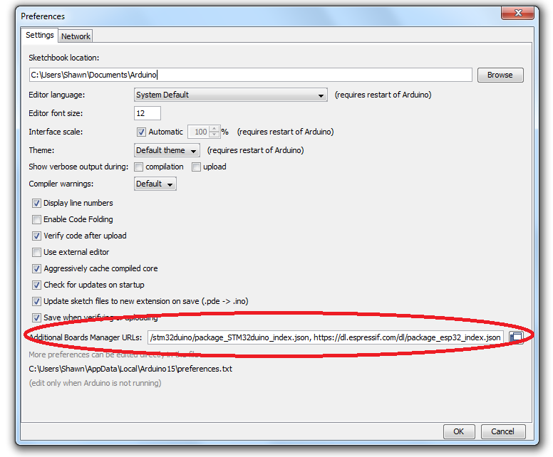 Figure 3 – Additional Boards Manager
Arduino libraries
This is the area where the Arduino really comes into its own for rapid embedded system development. There is a vast number of libraries available for Arduino-based hardware.
There are Arduino libraries for almost anything from Wi-Fi to LCD’s and OLED’s to all kinds of sensors such as an accelerometer, temperature and humidity sensors, pressure sensors, DAC, GSM and more.
Libraries are not just limited to external HW interfacing either. For instance, there are libraries for accessing remote MQTT servers, or for doing multitasking, and much more.
Just bear in mind that Arduino libraries are user-contributed, and some are better written than others. Some libraries will just not work as expected, and need to be tweaked.
Fortunately, Arduino libraries are actually simply C++ source code modules that are meant to be compiled with the rest of the application. Thus, they can be modified, and, in some cases, they actually must be modified.
For example, the library may have embedded a filename, or it has a predefined IO pin dedicated to accessing an external hardware, but did not provide functions to allow the user to change these to suit the intended application.
The path to the libraries are found by going to File > Preferences. A pop-up as shown in Figure 4 will appear.
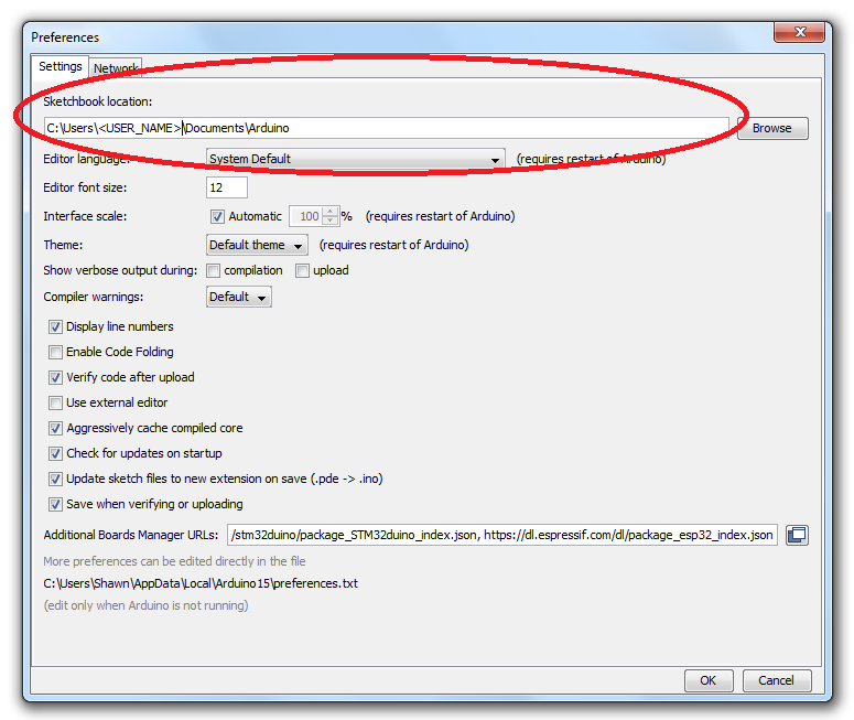 Figure 4 – Sketchbook location
In the folder listed in “Sketchbook location:,” there will be a folder named “Libraries,” and inside this folder will appear many folders, each containing an already installed library.
Choose the library of interest. Inside its folder there will be a folder named “src.” This contains the source files of the library.
Two ways to install an Arduino library:
If the library is included in the library manager, then just go to Sketch > Include Library > Manage library. This is shown in Figure 5 below. Clicking on “Manage Libraries” will bring up a pop-up that can be scrolled through to select the library to install. A typical library selection pane is shown in figure 6 below.
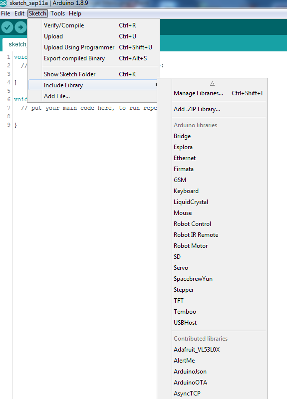
Figure 5 – Getting to the “Manage Libraries” menu
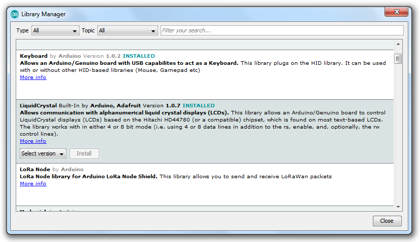 Figure 6 – Typical library manager selection window
Alternatively, if the library is not included in the Library manager, then download the zipped library.
Instead of selecting “Manage Libraries…” as shown in Figure 5, choose “Add .ZIP Library…,” and follow the instructions from there.
Can You Use an Arduino in a Commercial Product?
Yes, since Arduino is open source you can legally use one in a commercial product.
But, the real question is should you use one inside your product?
As the name implies, development kits like Arduino, are primarily designed for development and early prototyping, and not for mass production.
Why shouldn’t you use them for production? It generally comes down to three reasons: cost, size, and power consumption.
There are a few exceptions, though, where an Arduino may be a viable production solution. If your product is larger sized, has a high retail price, is not battery powered, and doesn’t need any custom PCB.
Impact on product cost
An Arduino Uno costs about $20. If you instead designed your own custom PCB with the same functionality, it would cost only a few dollars.
For example, the ATMega328P is the microcontroller used on the Uno. This chip only costs a little over a dollar at low quantities. There are also lower cost microcontrollers available with similar or better performance.
The other main chip on the Uno is a USB-to-UART converter chip. This can be eliminated for a production product since the ability to program via a USB port using the Arduino IDE is no longer required.
This just leaves a few really low cost components such as a linear regulator, a crystal, and any connectors. The passive components (resistors and capacitors) only cost pennies.
If you were going to replicate an Arduino exactly then you’d also of course have the cost of the PCB itself and the cost of soldering on the components. However, since you will likely also still require a custom PCB for other parts of your circuit, this cost is absorbed into the cost of your custom PCB.
Regardless of the development kit, they will always be considerably more expensive than designing your own custom PCB solution.
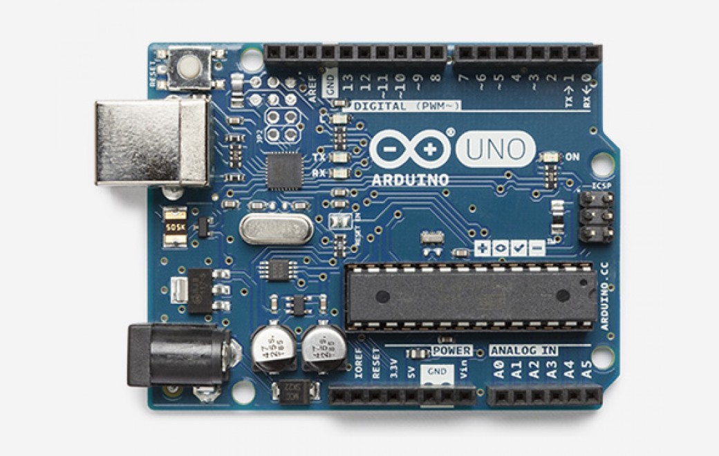 Figure 7 – The Arduino Uno is too large, expensive, and power hungry for use in most commercial products.
Impact on product size
The other downside to embedding a development kit like an Arduino into your product is the large size. An Arduino is quite large, and they were never designed with small size as a priority.
For example, if your product is a smart watch, then obviously these kits aren’t practical at all. Good luck fitting an Arduino in a watch! In fact, I’d say these kits are too large for probably 80% of products.
In addition to their large size, they also likely include functions or features that you don’t require. These features may significantly increase their size.
For example, an Arduino Uno uses a large USB type-B connector, but you may wish to instead use a small microUSB connector.
If you don’t require these features for your own product, then you are better off without the additional size and weight that they add to any product.
Impact on power consumption
Not only do any unnecessary functions add cost and size to your product, but they also increase the power consumption.
This isn’t critical if the product is powered from an external power source. But it becomes very important for battery powered products.
For example, the USB-to-UART chip used on the Arduino Uno can consume an extra 20mA of current when active. For a product running from a small battery this can have a significant impact on battery life.
Whether it is additional cost, size or power consumption, it rarely makes sense to include unneeded functions in your product.
How to Design a Custom “Arduino” Board for Mass Production
Despite the large variety of Arduino boards available, they can’t always be used in an embedded design, usually due to space restrictions and/or profit margin.
In such cases, it is still possible to stay within the Arduino ecosystem while having a customized board.
The idea is to simply embed the Arduino microcontroller in the custom board. The thing to remember here is that, at the end of the day, regardless of the code development process, a binary file is created.
Once this is loaded to the microcontroller, it will behave exactly as it was programmed to do, whether it’s an Arduino board or a custom board.
For the hardware, a device programmer is needed for the target microcontroller. There are many device programmers available to choose from as shown in Figure 8 below.
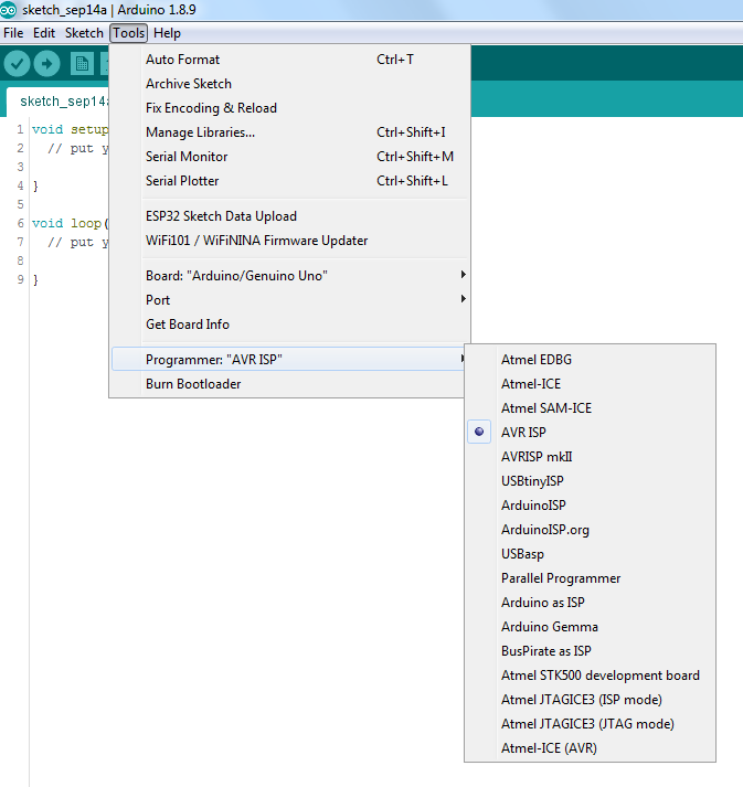
Figure 8 – Device Programmer list from Arduino IDE
This list is not exhaustive though, and there are many others not listed that would work as well.
Next, choose a board that has the same microcontroller as the one to be used in the custom board. The custom board should be designed using the same pinout as the chosen board.
For example, the Arduino Uno pinout is shown in Figure 9 below. Most pins have multiple possible uses that can be selected in the application code.
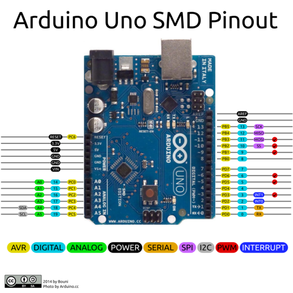
Figure 9 – Arduino Uno pinout
After that, write and debug the application code, using Sketch > Verify/Compile until it compiles without errors. The last step is to do Sketch > Export compiled Binary.
In the sketch folder, there will be several files, including .ELF, .HEX or .BIN files . These are the files that the device programmer will need in order to program the microcontroller.
Since each device programmer works differently from the others, its user manual should be consulted to get the specifics on how to use it to program the microcontroller.
Finally, note that since the Arduino IDE is still Atmel-centric, it does not list device programmers for non-Atmel microcontrollers such as ARM Cortex 32-bit microcontrollers from ST Microelectronics.
These are quite powerful microcontrollers that can also use Arduino as their development platform. These microcontrollers, if supported by the IDE, can be programed by using a ST-Link V2, or a functionally identical, but cheaper, clone. Click here for the software utility for loading the bin file.
To program these microcontrollers, simply connect the SWCLK and SWDIO pins of the device programmer to the corresponding device pins. Of course, VCC and GND have to be connected as well.
You should now understand that it is possible to use Arduino to develop embedded applications, even commercial ones. It is a viable alternative to using the native development platform of the embedded microcontroller.
That’s because Arduino is basically just C/C++ in disguise, designed to provide a higher level of abstraction. Of course, this removes the insight that comes from a more intimate knowledge of the underlying hardware.
However, this can be an acceptable compromise if you need to speed up the development of your application.
Design the schematic for custom Arduino board
So you’ve decided to progress from an Arduino prototype to a consumer product that is ready for sale. There is a lot of engineering work required to turn it into a product that can be manufactured and sold. So I’m going to show you the most straightforward strategy to transition from an Arduino prototype to a truly sellable product.
First off, you want to use the same microcontroller as used in the Arduino. Although there may be higher performance and lower cost microcontrollers available, the simplest option is to just use the same microcontroller.
There are two key reasons why using the same microcontroller is the easiest option. First, the firmware you’ve already developed is more easily ported over to the manufacturable version of your product.
Secondly, Arduino is open-source hardware so for the most part the circuit schematics can be simply copied.
Selecting the microcontroller
The large majority of Arduino models are based on an Atmel AVR 8-bit microcontroller (see Figure 11 below).
The exceptions are the Arduino Due, Zero, MKR1000, and MKRZero all of which are based on 32-bit ARM Cortex-M architecture microcontrollers from Atmel (ARM Cortex-M is a very popular architecture implemented by many microcontroller manufacturers).
For the remainder of this article we’ll be specifically dissecting the Arduino Uno which uses the Atmel ATmega328 microcontroller.
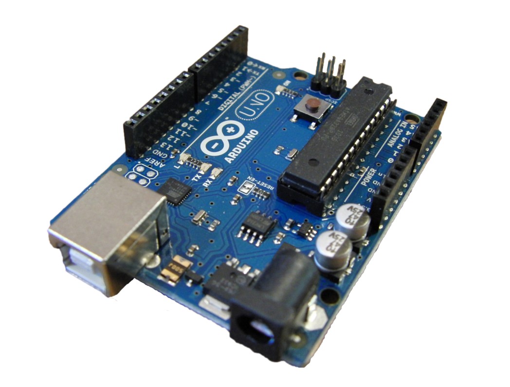 Figure 10 – Arduino Uno uses an ATmega328 microcontroller with 32kB of Flash memory
The ATmega328 used in the Uno is a through-hole DIP (Dual-Inline Package) version in a socket. Use of a socket allows the microcontroller to be easily swapped out if it becomes damaged. A socketed microcontroller may be a good idea for a development kit, but not for a production product.
First of all, a DIP package is going to be significantly larger than a SMT (Surface-Mount-Technology) package, especially with the added size of a socket. Secondly, your PCB assembly costs will be lower if you avoid through-hole packages entirely.
Finally, DIP packages tend to be more expensive since they are not generally used in high volume production.
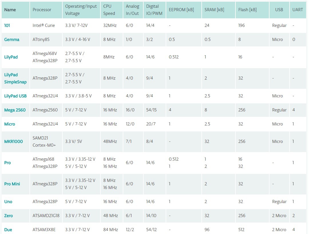 Figure 11 – The microcontrollers used in the various models of Arduino.
There are numerous microcontrollers on the market that are more powerful and cheaper than the ATmega.
For example, there are 32-bit ARM Cortex-M microcontrollers available for about half the price of the ATmega328. Not only are they half the price but they include twice the memory and several times the processing power.
However, using the same microcontroller as your development kit will make the transition significantly less complicated. Both the hardware design and the software development will be simplified.
Schematic review of Arduino Uno
One of the great things about the Arduino is that it’s an open-source platform. This means that you can easily view both the schematic and PCB layout for any of the Arduinos. Let’s start by looking at the schematic circuit for the Uno.
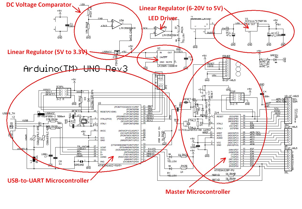 Figure 12 – Marked up schematic diagram for an Arduino Uno.
Looking at the schematic for the Arduino Uno you’ll see there are two primary integrated chips: U3 and U4. U4 is an ATmega328P microcontroller, and U3 is an ATmega16U2 microcontroller. But wait a second, why are there two microcontrollers?
The ATmega328P (U4) is the primary microcontroller. The second microcontroller (U3 – ATmega16U2) is solely there to provide a USB to UART conversion function since the ATmega328P doesn’t include a built-in USB port for programming. Older Arduinos instead used a specialized USB-to-UART chip from FTDI called the FT232RL.
By changing the FTDI chip to the ATmega16U2 it not only lowers the cost of the Arduino, but it also allows advanced users to use the USB port for other types of devices such as a keyboard or mouse.
In general, a microcontroller based solution will provide more flexibility than a specialized solution like the FTDI chip.
As I will discuss later in regards to programming, with a custom microcontroller circuit you will no longer need a USB port in your design for programming purposes. So, if your product doesn’t require a USB communication for other purposes (USB charging is different), then you don’t need U3.
If you do require a USB port for your product then I would instead suggest you use a microcontroller that includes an embedded USB port, such as the ATmega32U4 microcontroller used on the Arduino Leonardo.
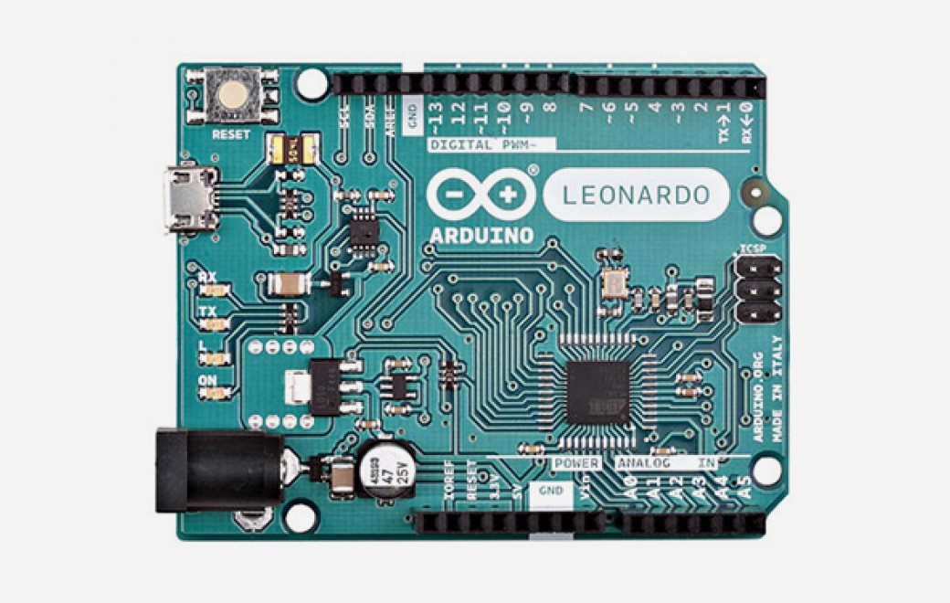 Figure 13 – Arduino Leonardo uses an ATmega32U4 microcontroller with a built-in USB port
That being said, the ATmega32U4 can be quite pricey, but you can get an ARM Cortex-M 32-bit microcontroller with USB functionality for a cheaper price.
Microcontroller support circuitry
Each of the two microcontroller circuits in the Uno consists of a crystal oscillator running at 16 MHz, various GPIO (General Purpose Input/Output) signals, multiple serial interfaces including one for programming, a power supply, and lots of decoupling capacitors.
U5 is a dual op-amp (operational amplifier) called the LMV358IDGKR from Texas Instruments. One of the two op-amps (U5A) is operated as a comparator since it has no feedback. This comparator is used to determine if the Arduino is being powered by the DC input or via the USB port.
If the 6-20V DC input voltage is present then the 5V supply is generated by an on-board linear regulator (as I discuss in detail shortly). On the other hand, if the 6-20V DC input is not present then the 5V supply voltage comes from the USB port.
So, if there is a 6-20V DC input voltage supplied then the positive input of the U5A comparator is higher than the negative input (3.3VDC). In this case the output of the comparator will be high, and PMOS transistor T1 will be turned off. This disconnects the internal 5V signal from the USB supply voltage.
If the 6-20V DC input is not present then the output of U5A will be low which turns on T1, thus the internal 5V supply comes from the USB port.
The other op-amp in U5 (U5B) is connected in a configuration known as a unity-gain feedback amplifier. This is a fancy way of saying that it has a gain of 1 which means it acts as a simple buffer.
Whatever voltage you put on the input of U5B is what you get on the output. The purpose is that now the output is able to drive a much larger load. In this case, this buffer is there simply to flash an LED whenever the serial programming clock (SCK) signal is present.
Power circuit
The power circuit for the Uno is based on an NCP1117 linear regulator from ON Semiconductor. This regulator generates a 5V DC voltage from the 6-20V DC input voltage and can source up to 1A of current.
The use of a linear regulator in this situation is fine for some products, but not if your product is powered from a battery, or consumes large amounts of current.
A linear regulator such as the NCP1117 is extremely inefficient when the input voltage is significantly higher than the output voltage. Being inefficient means it wastes a lot of the power by dissipating heat.
For example, on the Uno the input voltage can be as high as 20V, and the output voltage is only 5V. This means the input-output differential voltage is 15V. If you pull the maximum current of 1A from this regulator, the power dissipated by the linear regulator would be (Vin – Vout) * Iout = (20V – 5V) * 1A = 15W!
If the NCP1117 didn’t have an internal thermal shutdown feature, it would literally cook while trying to dissipate this much power. Regardless, you will waste all of this power as heat.
If you need to step-down a high voltage to a significantly lower voltage then a switching regulator is a much better choice. I won’t get into the details of switching regulators in this article, but they are many times more efficient than linear regulators. However, switching regulators are also considerably more complex than linear regulators.
On the Uno a LP2985 linear regulator from Texas Instruments is used to create a 3.3V voltage. The LP2985 is rated for 150mA of load current. This type of linear regulator is also called a Low-Drop-Out (LDO) regulator because it requires very little differential voltage from the input to the output.
Older, non-LDO linear regulators required the input voltage to be a few volts above the output voltage. However, from a power dissipation standpoint it’s best to operate a linear regulator with an input voltage close to the output voltage.
The 3.3V voltage is fed into a comparator (U5A) that is used to switch to USB power, if available, when no power supply is plugged in.
The LP2985 doesn’t dissipate that much power so a linear regulator is a good choice for this regulator. This is because the input-output voltage differential is only 5V – 3.3V = 1.7V, and the maximum current is only 150mA.
A very common strategy is to use a switching step-down regulator (also called a buck regulator) followed by a linear regulator. In addition to the increased complexity, the other downside of a switching regulator is it provides a “noisy” output voltage.
This is fine for many applications. However, if you require a cleaner supply voltage it’s best to add a linear regulator to clean up the output voltage from the switching regulator.
What about any shields?
You are probably also using some shields that will also need to be converted to a custom schematic. If the shield is providing wireless functionality then in most cases you are better off using a surface-mounted module which solders directly on to your PCB.
There are two reasons for using a module for wireless functions. First, the PCB for a wireless radio can be quite complex to lay out correctly. Secondly, the use of pre-certified modules will simplify the process of getting your product certified.
Other functions, such as sensors and motor controllers, are best accomplished with a custom circuit design.
Design the PCB layout for custom Arduino board
Now that the schematic design is completed, it’s time to turn it into a Printed Circuit Board (PCB). A schematic is simply an abstract technical diagram, but a PCB is how you turn your design into a real-world product.
Since the Arduino is open-source hardware the PCB layout design is available for reference. However, you will almost surely need to redesign the PCB for your specific product size requirements.
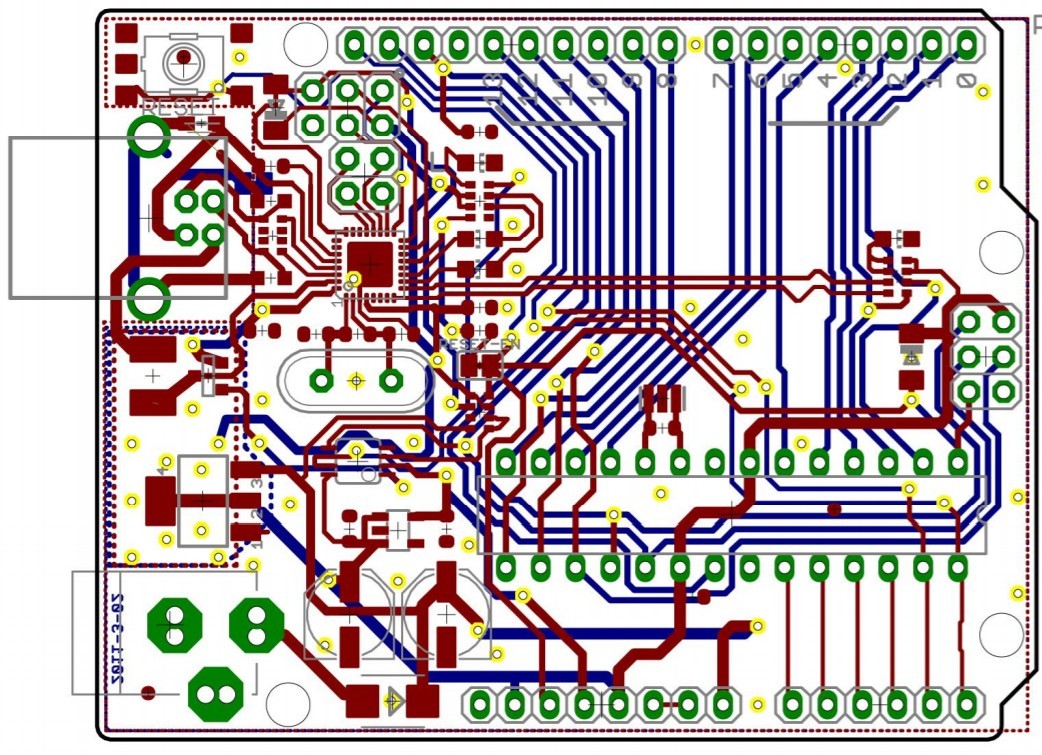 Figure 14 – PCB layout for the Arduino Uno
A microcontroller circuit with a clock speed of only 16 MHz, without wireless functionality, is a fairly simple PCB layout to design (assuming you know how to do PCB layout). Things become much more complicated once speeds approach hundreds of MHz, or especially GHz.
Be cautious about two things when laying out an Arduino Uno equivalent microcontroller circuit. First, the crystal and it’s two load capacitors need to be laid out correctly and placed as close as possible to the microcontroller pins.
Secondly, carefully lay out any decoupling capacitors so they are as close as possible to the pin that is being decoupled. Be sure to always review the microcontroller datasheet for PCB layout guidelines.
Order PCB prototype boards
Once the PCB layout is completed it’s now time to order the boards. However, before ordering any PCB prototypes you should really get an independent design review of the schematic and PCB layout.
Regardless of the designer’s experience level, an independent design review reduces the likelihood that mistakes will make their way into your prototype. I always get other engineers to review my own designs and so should you.
In the Hardware Academy you can get affordable feedback on your design from lots of expert engineers, including myself. We can also help you to find ways to simplify your product to lower your development, prototyping, certifications, scaling, and manufacturing costs.
In some cases you may have two different vendors make your boards. One vendor will produce the blank PCB’s, and then another supplier will solder the components onto the board.
In other cases, a single vendor will perform both steps. For example, Seeed Studio’s Fusion service can supply you with completely assembled boards at an incredibly affordable cost.
For your first prototype version I suggest ordering only 3-10 boards. This is because the first version will likely have various bugs that will need to be fixed.
In most cases it’s a waste of money to order a large quantity on the first version. Once you’ve tested and debugged the first version, then increase the quantity for the second order.
Develop the firmware for custom Arduino board
One aspect of an Arduino that is different than your own, custom microcontroller circuit is how the programming is done. An Arduino is programmed via a USB port. This allows it to be programmed from any computer without the need for special hardware.
On the other hand, a custom microcontroller is usually programmed via a serial port protocol such as SPI, SWD, UART, or JTAG. In order to program a microcontroller using one of these serial programming protocols you’ll need a special piece of hardware called an In-Circuit Serial Programmer (ICSP) or In-System Programmer (ISP).
You’ll also sometimes see “programmer” substituted with “debugger” since this hardware device also allows you to see the inner workings of the microcontroller for debugging purposes.
These devices are called In-Circuit or In-System programmers/debuggers because the microcontroller can be programmed directly in the system without any need to remove the microcontroller.
The old method of programming required the microcontroller be removed from the circuit for programming, then re-inserted back into the circuit. This is a very inefficient method of programming a microcontroller during development.
The AVRISP from Atmel is an example of an in-system programmer for the Atmel AVR line of microcontrollers.
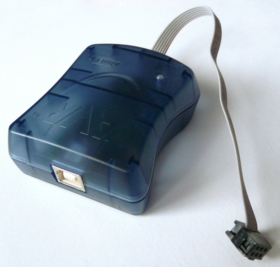 Figure 15 – The Atmel AVRISP mkII In-System Programmer (ISP)
This special programming hardware isn’t required for an Arduino since it is essentially already embedded in the Arduino. As already discussed, the Arduino Uno incorporates a USB-to-UART converter to allow programming via a standard USB port.
Once you have the necessary programming hardware it’s time to port over your Arduino sketch to native firmware code.
Just as with a custom microcontroller, an Arduino is programmed using the C language. However, programming is greatly simplified on the Arduino since it already contains a huge library of various functions.
For example, to setup a GPIO pin as an output on an Arduino, and then output a low logic level, you would use the following two functions:
pinMode(PinNumber, OUTPUT);
digitalWrite(PinNumber, LOW);
When you execute these two functions, the real work is performed by the library code behind these functions. For a custom microcontroller circuit the library code for these two functions must also be ported over to your microcontroller code.
Finally, remember that you don’t have to use the exact same microcontroller as your Arduino to simplify programming. Selecting a microcontroller from the same line of microcontrollers will still significantly simplify the transition from Arduino to production.
For example, porting your Arduino code over to any 8-bit AVR microcontroller will be considerably less complex than porting it over to a 32-bit microcontroller.
Test, debug, and repeat
It doesn’t really matter how good you are at designing circuits. Unless your product is exceptionally simple, you are almost guaranteed to make at least one or two mistakes in your design.
Be sure to account for this fact in your planning. That being said, accurately planning for debugging is extremely challenging since you are inherently dealing with unknown and unexpected problems.
Conclusion
Building a Arduino-based prototype is an easy way to start bringing your new electronic product to reality.
This article has shown you how to choose the right Arduino board for your product. You have also learned how to design a custom board that keeps many of the positive benefits of an Arduino platform, including the relative ease of developing new software applications.
An Arduino based design is not always the right option for every product, such as if your product requires a very fast processor, but for a large percentage of new electronic products it is one of the best ways to quickly build a Proof-of-Concept (POC) prototype without spending a fortune.
Your goal should always be to build something as quick and as cheap as possible, and then get these prototypes in the hands of potential customers for feedback before you begin spending big money on custom development.

Hi John,
this article is very helpful! Finally some insight on how to go from arduino’s with lots of wires to something commercially! Thanks!!
I have one question remaining. If you use the .hex file, created by the Arduino IDE, is that usable in commercial products without the obligation to share your code? Do you need to write all te code yourself than? What would be a practical approach?
Thank you Gabriel for the great feedback! Since Arduino is open-source using the .hex created by the Arduino IDE should not be an issue.
Documentation… both for the user, repairer, and the original developer to review in the future.
John, this is precisely the type of targeted, relevant content that made me become a Hardware Academy member. It’s right on target, detailed, and succinct. Bravo, keep doing what you’re doing my friend.
Wow thank you Josh for that amazing feedback! I’m so glad you decided to become a Hardware Academy member!
Another amazing article from JT! We’re living this life exactly and can confirm that every tidbit of advice is bang on. For folks just starting down this path – I’d only add that the devil is absolutely in the details – we’ve recently found a “bad” ESP32 library that’s been causing us all sorts of issues. There’s an update that only recently become available that “should” fix our issues – but it took some serious sleuthing to pinpoint the issue. But overall, our path to prototypes was made possible entirely by using the ESP32 MCU and 3D printing. Hope you can enjoy the same success.
Thank you Robinson for this feedback and for sharing your experience with the ESP32!
For comparison, the off the retail price of the Arduino Nano Every is $10.90, on average, what would be the final cost to have one hundred of the same boards sourced and fabricated?
After completing hardware design can I flash programs written in Arduino IDE directly through USB(In case of Arduino Leonardo) to the board or I have to write some boot codes to accept my program itself.
Thank you John, very informative. Any recommendations for a low cost module with Wifi?
Best Regards,
Beraa
Thanks for the comment. The Espressif ESP-WROOM-02 based on the ESP8266 is a great low-cost WiFi module. If you also need Bluetooth then the ESP-WROOM-32 (based on ESP32) is the way to go.
thanks alot, very useful.
if we omit usb-uart converter chip or mcu then how do we go about it. i’m only familiar with arduino usb way.
Hi Abba,
Thanks for the positive feedback!
You would want to use either a MCU with a built-in USB port, or program the MCU using a programming device like the ST-LINK. Normally, outside of Arduino most MCU’s are programming using a proprietary programming device that converts the USB from the PC to a MCU programming protocol such as JTAG or SWD.
Hi John, i am from Chile and you are help me so much, thank you!. This is process is what i am actually doing right now and it is good to see that there are somebody else doing this development process. I am very expectating for the article to “how to migrate from a 8-bit Arduino to a more powerful, and typically lower cost, 32-bit microcontroller”.
Thanks Arturo! I appreciate the feedback. I’ll definitely be creating more content along these lines including the article you referenced on upgrading to a 32-bit microcontroller. I’m also working on creating free instructional videos that show me designing a various circuit boards from start to finish.
Best wishes,
John
Thank you John for sharing such a grate article. When I first met Arduino, I thought how nice and easy would be to get all this open source files and create my own ideas. With you now showing that this is feasible, it just makes nice sense !
Best regards,
Panayiota
Hi John,
Many thanks, an awesome idea to write this article because, you had condensed a lot of useful info in the same place.
Thank you Daniel. This is a topic I will be writing even more about in the future.
John
Thanks John,
I enjoy your articles as they make a lot of sense… One of the things I have realized is that it is way too expensive to do creative design, prototyping, etc, in the USA… Our organization just can not afford the high costs for somewhat simple electronic designs here… It really is our intention to do design and production in the USA… But to bring back technology here is just not cost effective for a small business to support people here… But, it is something I would love to do… China has been very helpful and easy to connect with which allows us to create/production… I am in the medical business and our objective is to have high quality/Low cost as we different than the typical medical device company…
Keep up the great work…
Victor Wedel
Hey Victor,
Thanks for the feedback Victor. Development in the US is definitely more expensive, but for many people it still makes the most sense. Personally I’ve found China to be great at later stage development (for example, optimizing a prototype for manufacturing). But for early stage development I’ve found it to be slow and some times problematic. But I do understand the need to reduce development costs.
Because so many entrepreneurs are obviously cash-limited, I’ve recently started recommending that it may be best to have development done in Asia but then have an independent engineer review their work. This is one reason I started offering independent design reviews a while back. So if you need an independent engineering review please keep me in mind.
Best wishes,
John
Dear Victor, John,
Malaysia could be another place which you can opt to have a wholeset of Design to Manufacture site. The curren Government has strict laws and got lots of pool of professional supports (young grads, skillfull technical personnel) and of course the infrastructres are well taken cared. Please contact me if need help. I am also keen into DtM concept.
Thanks
Dinesh
Hi John, i wanted to simply express my sincere gratitude for the work you put in writing your articles. Your content is of a great quality. In simple words you are able to outline and explain the key concepts involved in the industry of electronics fabrication. This is wonderful. I wish you all the best, Alex !!!
Thank you Alex! I put an incredible amount of work into creating all of this content, so I truly appreciate feedback like yours. My goal is to help as many entrepreneurs/startups as possible, so it’s always nice to hear positive feedback from my readers.
Best wishes,
John