
Introduction to the ESP32 – From Prototype to Production
The ESP32 is a popular family of wireless microcontroller chips developed by the Chinese chip maker Espressif.
It’s a very affordable solution for use in commercial products especially considering its high level of performance and extensive features.
The Espressif ESP WiFi family of microcontrollers started with the original ESP8266 which embedded a single-core microcontroller with a WiFi radio.
This chip was a phenomenal success especially with the electronics maker community.
Then in 2016, Espressif released the ESP32 which primarily added a Bluetooth radio and an optional dual-core microcontroller.
Even though the ESP32 included lots of new capabilities compared to the ESP8266, the price increase was minimal.
So the choice was clear, and eventually the ESP32 mostly replaced the ESP8266.
Selecting an ESP32 wireless microcontroller used to be an easy thing to do since for several years there was only one model available.
But, that has all changed in the last few years, with multiple new models being released starting in 2020.
These new models give you more design flexibility, but they make the selection process much more challenging, and in fact quite overwhelming for many.
Selecting the Best ESP32 Model for Your Project:
There are three stages of ESP32 solutions you need to be aware of:
- SoC (System on a Chip) – This is the bare ESP32 chip you would purchase if doing a fully custom design.
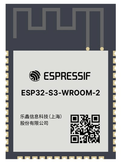
- Modules – An ESP32 module is designed to be soldered onto a custom PCB so it eliminates the need to custom design the ESP32 circuit and antenna. Modules are also pre-certified so they simplify the certification process compared to using an SoC in a custom circuit, especially those with a built-in antenna.
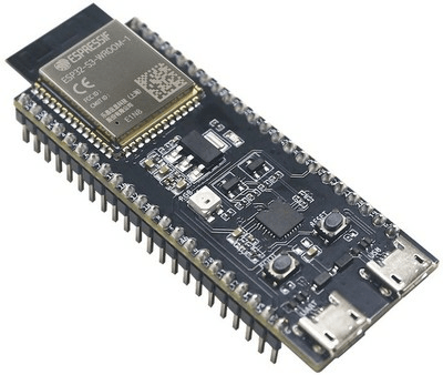
- Development kits – These are larger boards that include the embedded module, but they connect the various I/O to header pins for easy access during early development.
When selecting the ESP32 for your project you want to start at the most fundamental level with the SoC, and then work your way up to the module, and then the development kit.
Selecting the SoC:
Designing with the SoC is usually only done after you reach a few hundred thousand production units.
For lower production volumes it’s almost always best to start off using a pre-certified module.
A custom SoC design only makes sense at higher production volumes when the increase in profit margins outweighs the extra cost of certification that’s required for a custom wireless design.
Although most projects are best off using a module, we’re going to start by selecting the ESP32 SoC.
The original model of the ESP32 is still available and isn’t yet marked as not recommended for new designs. But for various reasons it’s not the version I recommend for most projects.
For years the only decisions you had to make were if you wanted a single or dual-core version, and choosing the amount of memory needed, and the package.
But, then lots of new models in the ESP32 family came along with many significant differences.
They’ve now added the ESP32-S, ESP32-C, and ESP32-H chip families.
The additional options are great to have, but they also drastically complicate the selection process.
ESP32-S Series:
The S series is intended to be the best replacement for the original ESP32, whereas the C and H series are more specialized models.
The ESP32-S series is based on a new and improved version of the 32-bit processor core called the LX7, whereas the original ESP32 model used the LX6 version of the core.
The S series has a lot of other improvements compared to the original ESP32 including improved security features.
One of the most desirable features that’s always been missing from the original ESP32 is USB.
The original ESP32 doesn’t have a native USB port, so it requires a separate USB-to-UART converter circuit with a speed limited to only 3 megabits/sec.
But, this isn’t necessary with the S series which adds full-speed USB On-The-Go, which theoretically can do up to 12 megabits/sec.
The On-the-Go just means it can switch between the roles of host and device.
Other improvements in the S series include more GPIO pins, better low-power capabilities, and the ability to add up to 1GB of external RAM or Flash memory.
So the S series is faster, more secure, has full-speed USB, more GPIO pins, and supports more memory than the original ESP32.
There are currently two versions in the S series: S2 and S3.
The S2 is a single core and supports only WiFi, not Bluetooth.
On the other hand, the S3 is a dual-core microcontroller that supports both WiFi and Bluetooth 5, and it comes with more embedded Flash memory.
ESP32-C Series:
The C series is fundamentally different from the ESP32’s we’ve discussed so far.
Its design arose out of two things: pandemic related supply chain issues and the popularity of small, low cost IoT products like smart plugs.
Although the ESP32 S series is impressive and intended to be a replacement for the original series, one negative is it comes in a larger package.
The feature that most significantly increases the chip size is the amount of embedded Flash memory.
Both models of the S series come in packages measuring 7mm x 7mm, whereas the C series is available in packages as small as 4 mm x 4mm or 5mm x 5mm.
So Espressif decided to design a new ESP32 model that requires less memory and could be smaller and cheaper.
Apparently that was the motivation for the creation of the C series.
The biggest change they made to accomplish these new design priorities was using a totally different processor core.
The C series uses a RISC processor instead of the processor core used in all of the previous models.
The C series comes in three versions including the C2, C3, and C6.
The C2 has a single RISC core that only operates up to 120MHz.
It supports both WiFi and Bluetooth 5 but it doesn’t include USB, and the security features included are minimal.
The C2 doesn’t appear to be stocked by any of the big component distributors, so I would avoid using it in most cases.
The C3 on the other hand operates at up to 160MHz, includes a full-speed USB port (although without OTG like the S series), and has much better security features.
The C3 supports both WiFi and Bluetooth 5.
The C6 version uses the same 160MHz core as the C3, but it has an additional low-power RISC core that runs at only 20MHz.
The C6 also supports WiFi 6 whereas all of the previous versions we’ve looked at, including the S series, only support WiFi 4.
In addition to WiFi 6 and Bluetooth 5, the C6 also adds wireless support for Zigbee and Thread protocols as well.
Overall, the C series primarily makes sense if you need the smallest possible chip size at the lowest cost, or perhaps if you need the ZigBee or Thread support provided with the C6.
ESP32-H Series:

Next is the ESP32 H series which currently consists only of the H2 version.
The H2 is an extension of the C series and uses the same RISC processor core, except it’s only running at 96MHz compared to the 120-160MHz speeds of the C series.
The biggest difference between it and every other Espressif chip is it doesn’t include WiFi.
Instead, it only supports Bluetooth, Zigbee, Matter, and Thread.
Due to the lower throughput speeds of these protocols compared to WiFi, the ESP32-H2 can run at a lower clock speed which consumes less power.
Selecting the module:
Once you have the ESP32 SoC selected for your project, you want to select the best module for your project that uses this SoC.
Fortunately, this part is pretty easy once you’ve selected the chip itself.
The main decision you need to make is whether you want a module with a built-in PCB antenna, or one with a connector for an external antenna.
If the internal antenna’s performance meets your requirements then I’d select a module with a built-in antenna, because this simplifies your design and the certifications process.
Selecting the development board:
Once you’ve selected the module, it’s now an easy matter to select the development board (sometimes called a kit) that uses that module.
The development board is just a larger PCB board that brings all of the I/O out to header pins.
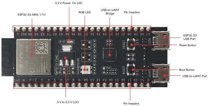
The development board also includes the USB-to-UART converter for easy programming, and a linear regulator to step down the 5V USB supply voltage to the 3.3V required by the ESP32.
This USB-to-UART converter is still included on the development boards for the models that include a native USB port such as the S series, C3, C6, and H2 models.
The development boards for these models commonly come in two versions.
One version only includes a single USB connector that goes through the USB-to-UART converter circuit and is limited to only 3Mb/s.
The second version adds on an additional USB connector that connects to the native USB port and can do up to 12 Mb/s.
Either USB port can be used for programming.
My final advice on selecting the best ESP32 for your project:
For most projects you’ll likely want to go with the S2 or S3 models.
Choose the S2 if you only need WiFi. Otherwise, choose the S3 if you also need Bluetooth or an additional processor core.
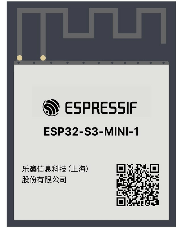
For the S series I’d suggest the MINI module versions which come in both S2 and S3 flavors with either a built-in antenna or a connector for an external antenna.
Three Stages From Prototype to Production
One of the reasons the ESP32 family is such a great platform for new product prototyping is that Espressif doesn’t just manufacture the bare chips.
They also offer pre-certified ESP32 modules and development kits as we’ve already discussed.
By sticking with the same microcontroller core all the way from your early POC prototype through to mass production you can more easily transition your firmware code between the various stages.
There are three stages to prototyping a new product with the ESP32.
You will progress through these three stages in the opposite order than you did when you were selecting the best ESP32 model for your project.
So, start with the development kit, then the module, and finally (maybe) the SoC.
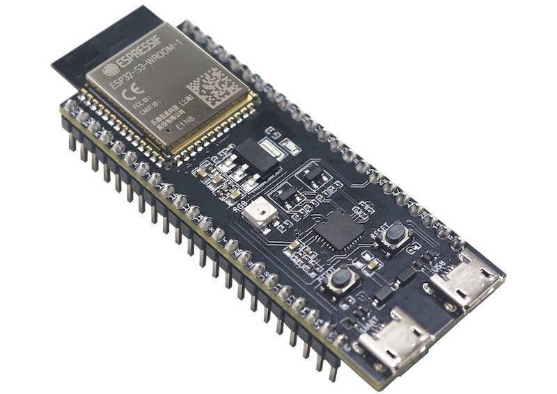
Stage #1 – Develop the early prototype using a development board incorporating an ESP32 module.
At this stage you will create your early Proof-of-Concept prototype using an ESP32 development board.
This development board is usually mounted on a breadboard or solderable proto-board so you can connect it as needed to the other components.
With this early, and usually quite ugly, prototype the goal is only to test and prove the functionality.
That’s why this type of prototype is also commonly called a works-like prototype.
Due to the use of a large development board and likely an even bigger breadboard, this early prototype rarely fits in the space required for your actual product.
Stage #2 – Design your own custom PCB and then solder an ESP32 module directly onto this board.
The two main reasons to use a wireless module instead of a custom SoC based circuit are:
- A module reduces design complexity
- A module reduces certification complexity and costs
The most complex part to design for a custom wireless circuit is the feedline between the transceiver chip (ESP32) and the antenna or antenna connector.
But, this design complexity is eliminated by using a module because it already includes either a built-in antenna or an antenna connector.
Also, since the wireless portion of your design is handled by the pre-certified ESP32 module, the FCC will classify your end-product as a “non-intentional radiator.”
Non-intentional radiator certification is much cheaper and simpler to obtain than full “intentional radiator” certification.
Stage #3 – Design your own custom RF circuit using the ESP SoC bare chip.
Typically, this final stage is only necessary for designs with extreme size constraints, or once you reach high production volumes and you need to squeeze out more profit margins.
This stage requires expensive full FCC “intentional radiator” certification so it should be avoided initially, and for most projects modules are the best option for production.
ESP32 Firmware Programming
There are two main choices for ESP32 firmware development: the Arduino platform’s ESP32 support, or the official ESP-IDF firmware package maintained by Espressif.
There are pros and cons to either approach, but here’s a brief summary of considerations when making your choice.
Arduino IDE
Arduino’s IDE main advantage is its portability. If you feel that you will want to move your application to another platform entirely, Arduino’s consistency across boards will make that process smoother.
Additionally, its platform provides user-created libraries for components you may want to use in your application.
In short, if it works, using the Arduino IDE can speed up the software development cycle.
See this other article of mine for more details about programming the ESP32 using the Arduino IDE.
ESP-IDF:
ESP-IDF has the immediate and obvious benefit of being maintained by Espressif, so it’s most likely to match the ins and outs of the hardware most closely.
In my personal anecdotal experience, ESP32 is one of the more buggy platforms on Arduino, so using the ESP-IDF may be the better option for many applications.
While ESP-IDF is a more advanced programming experience, it’s also more powerful.
This means any problems you run into are far more likely to be user error rather than some bug in the library or some hardware incompatibility that was missed in the Arduino implementation.
Additionally, ESP-IDF leverages FreeRTOS to provide a multi-threaded application experience, which may be familiar to developers coming from other firmware applications.
Also note that the two options are not mutually exclusive. Arduino libraries can be brought into an ESP-IDF project, and Arduino’s implementation attempts to bring in most of ESP-IDF’s features.
Your personal decision will be heavily based on your team’s composition as well as your product’s constraints and requirements.
The online documentation provided by Espressif is excellent, and ESP-IDF includes a variety of examples that will help users get started.
Conclusion
Designs based on an ESP32 wireless microcontroller can be as custom or convenient as your product needs, throughout all the various stages of development.
It’s a very low-cost solution that has become extremely popular for both makers and product developers.
This popularity helps to ensure that there is extensive help and documentation available online.
Not only is the ESP32 a fantastic option for building an early POC prototype, but it’s also a great choice for mass manufacturing, whether you use the module or the bare SoC chip.
