
Teardown of an ESP32-based WiFi Smart Home Product – The Shelly i4
Customer demand for smart homes just keeps growing, and home automation devices are central to controlling any home environment.
Yet, there is an ever-increasing complexity added when multiple devices begin to connect to your smart home.
Want to open the blinds, turn on the coffee pot, and switch your LED lights to a certain color at the same time?
Well, controlling multiple devices like these is exactly what the Shelly i4 Plus is built for.
Built to be small enough to fit behind a switch plate, Shelly’s i4 Plus is a Wi-Fi connected smart switch detector for homeowners to program or automate anything electrical in their house – things like lighting, fans, and appliances.
The Shelly Plus i4 is an input reader device and it does not contain relays.
It’s specifically designed to read the position of wall switches for controlling other smart home devices, so it would be placed behind a wall switch panel.
Shelly also offers WiFi-enabled relay modules based on the ESP32 that are used for actually turning on/off devices.
In this article, we’ll be taking apart this tiny smart switch detector to get a better look at the internals and see what goes on under the hood.
General specifications
The general specifications for this device include a couple of key components:
- Power Supply: 110-240 VAC, 50/60 Hz
- Power Consumption: <1W
- MCU: ESP32 (4MB of Flash)
- Firmware capabilities: Webhooks, Scripting, and MQTT
Teardown of Shelly i4 Plus
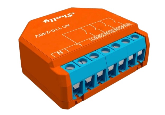
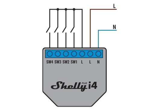
The Shelly has seven total screw terminal inputs.
Four of these are for detecting the status of the independent switches connected to it, and the other three act as the AC in line to power the device directly from the wall.
Two of those three are used as the “Line,” while the other is used as a “Neutral.”
The diagram on the outside of the case shows a good view of what the layout looks like.
On the bottom of the switch, we see a couple of safety markings, as well as the maximum acceptable AC voltages and temperature ranges for the device.
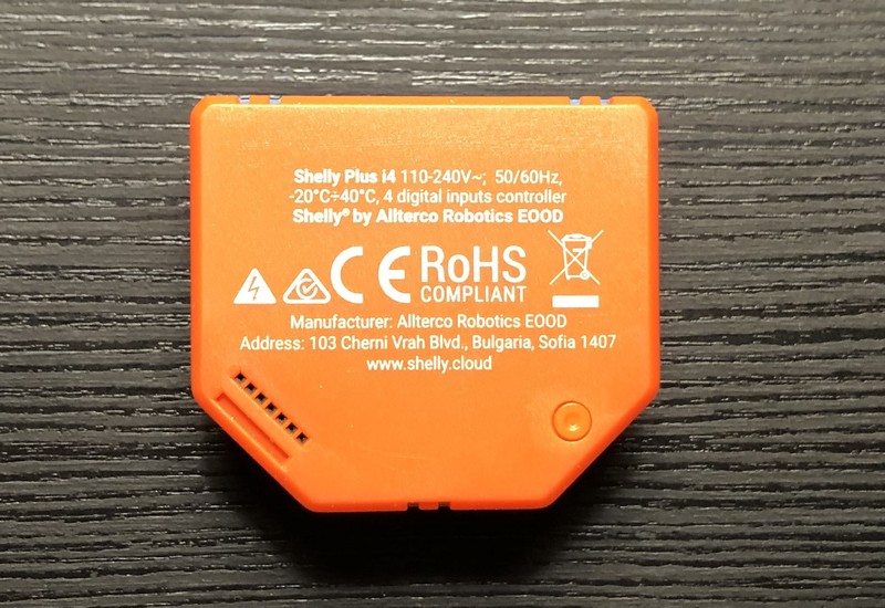
The RoHS compliant label and the “CE” marking are commonly seen on electronic products and signify that the device is certified to be sold, in this case, within the European Economic Area (EEA).
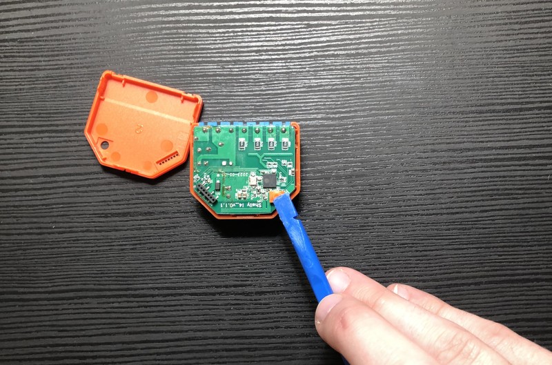
Now, let’s get to opening the device and see what’s inside!
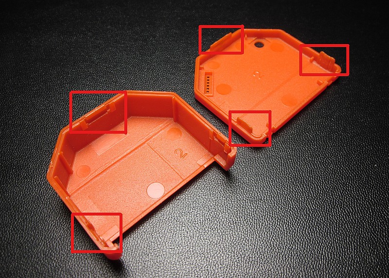
The first thing you’ll notice is that the outside of the switch is made of plastic, and there doesn’t seem to be any screws holding the plastic enclosure together. So, we can safely assume the two pieces are held together by tabs.
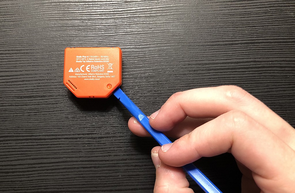
Tabs (pictured below), also called a snap-fit, are one solution for clasping shut an enclosure just using the plastic parts, without needing metal screws or glue.
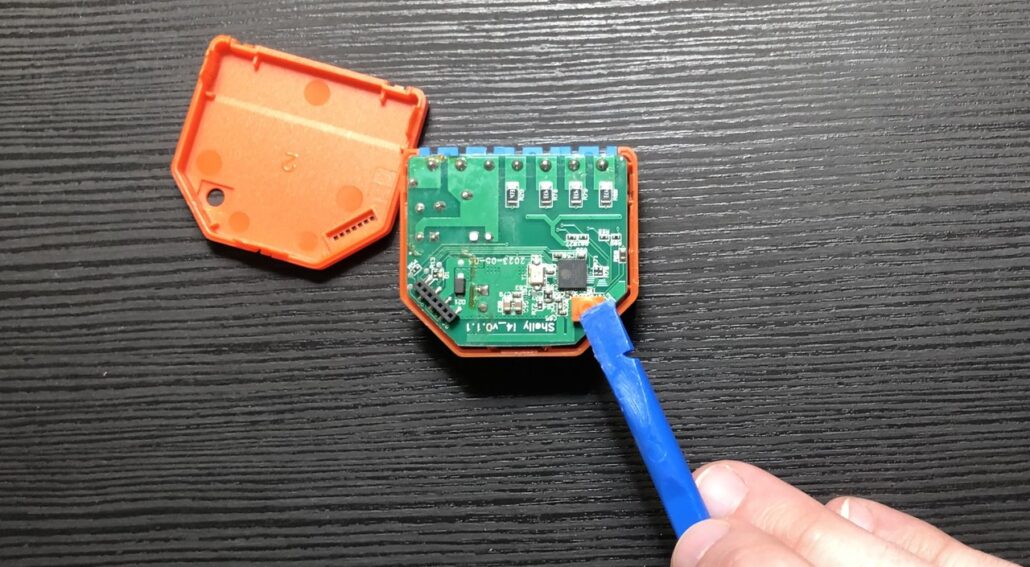
After prying open the seam of the device, we get our first look inside the smart switch to reveal our main MCU and some other components.
Let’s look closer at how our AC voltage coming from the wall gets converted into DC to be used by our microcontroller.
On the back side of this PCB, you’ll see a section containing an IC, a couple of capacitors, a fuse, and an inductor.
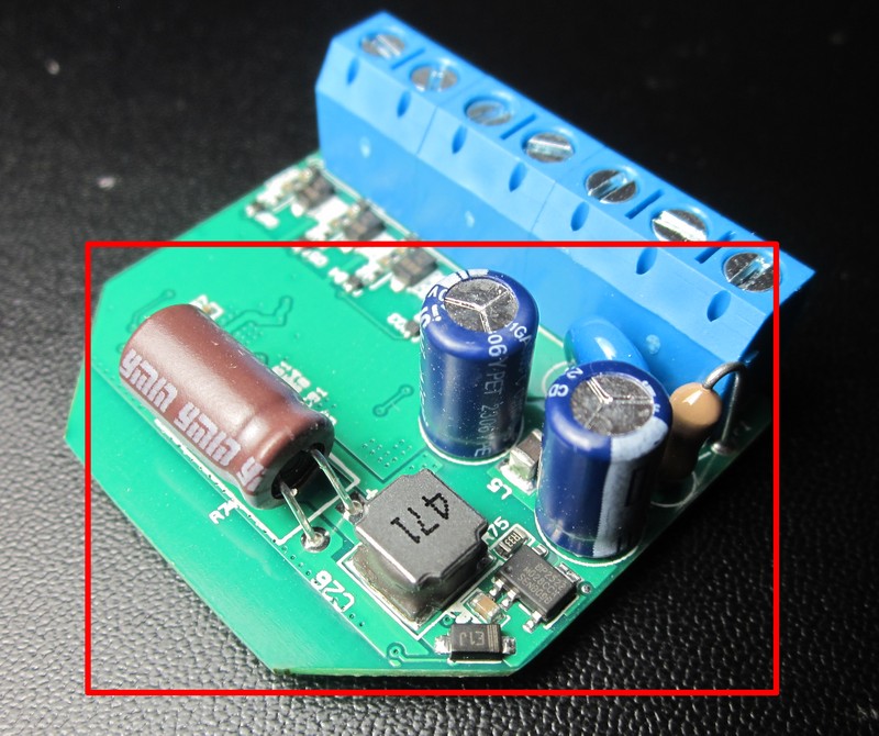
Let’s trace these components out and figure out how everything works.
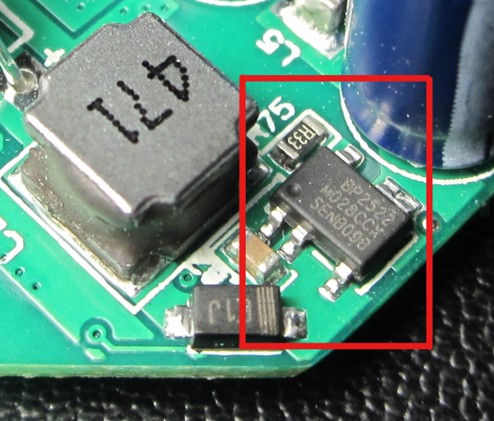
Taking a look at the IC, we see the following marking on the top: BP2522.
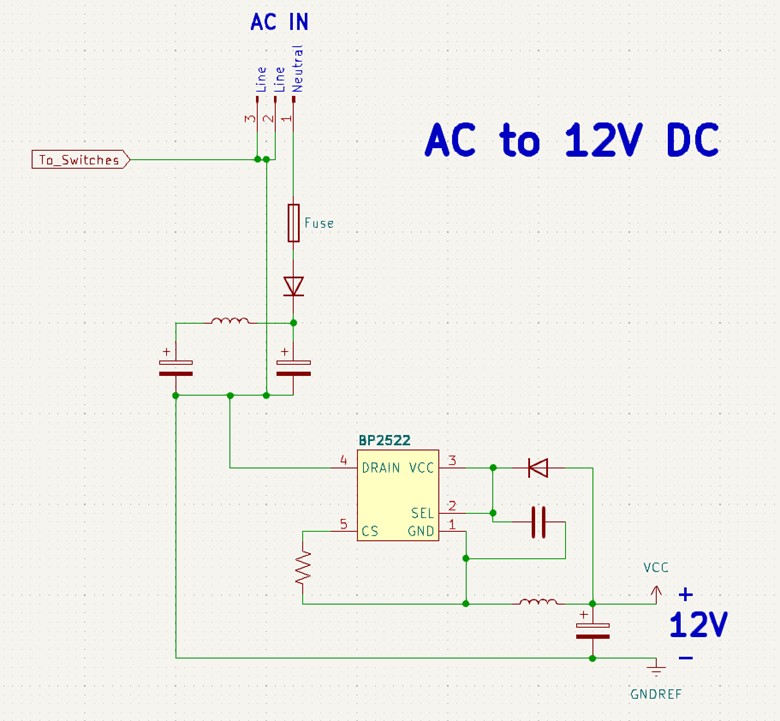
You can use a quick google search to find out that this IC is from Bright Power Semiconductors.
It’s a non-isolated, step-down, constant voltage driver IC, which takes the incoming AC voltage from your Neutral and Line wires in your home and converts this to 12V DC, as seen below:
Then there’s another IC under the large 330 uF capacitor which will step-down the 12V to the 3.3V required by the ESP32 IC, as shown below:
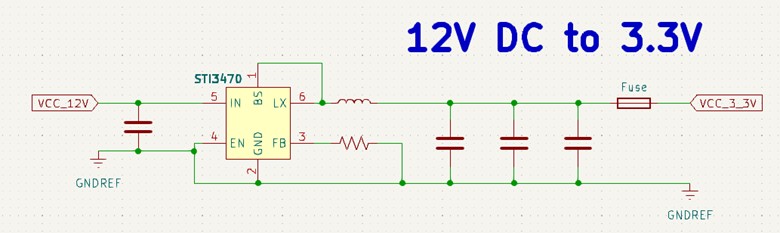
The Shelly i4 Plus uses a remarkably similar design to what’s recommended in the datasheet.
For many power applications, it’s typical to see designers use what’s recommended in the datasheet for specific ICs.
Though the recommended design typically works for many applications, it’s still up to you to determine whether the design meets your requirements.
Note that in recommended designs, you’ll typically see specific capacitor, resistance, or inductor values, and these may change depending on your application.
Once power is brought down to 3.3V, we see an almost identical set up to the reference design for the ESP32 IC.
Once again, it’s pretty common for a designer to trust the manufacturer’s reference design.
You can see that an Inverted-F Antenna (IFA) design is chosen as the antenna connected directly to the ESP32.
These antennas provide great gain for their size, and despite the bandwidth being quite small, it’s perfectly adequate for Wi-Fi and Bluetooth in the 2.4 GHz range.
For the pairing process, the Shelly i4 Plus hosts a web server where the user can connect to the AP (Access Point) from their phone to input their home Wi-Fi credentials.
This is one of many ways to securely create the pairing process for passing credentials from a user to a device.
A picture of the layout of the ESP32 is shown below, and you can find more information on the reference design used for the ESP32 IC here.
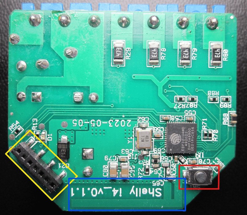
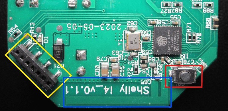
The areas identified by the colored boxes in the image above are:
Yellow: Shelly Proprietary Connector
Blue: Inverted-F Antenna (IFA)
Red: Reset Switch
Up next, we get to the terminals that detect the status of our wall electrical switches.
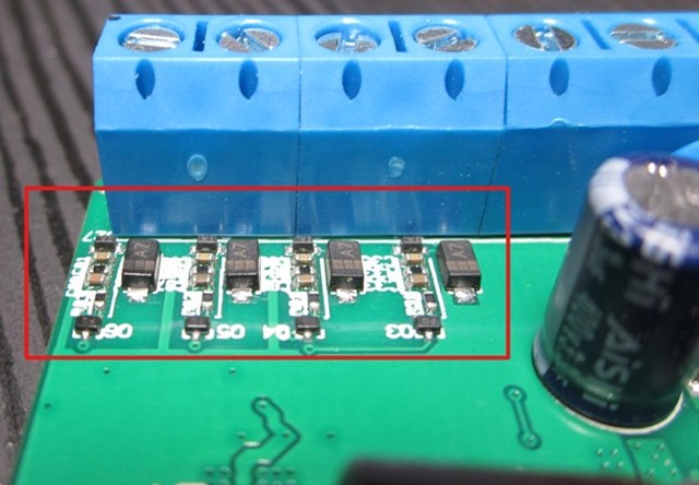
These terminals can detect a switch being open or closed, as shown in the diagram below:
This means that the GPIO pins for the ESP32 are acting as inputs, since the i4 device is specifically used to read the switches and then via WiFi toggle other systems or devices in your home.
Let’s take a closer look at this section:
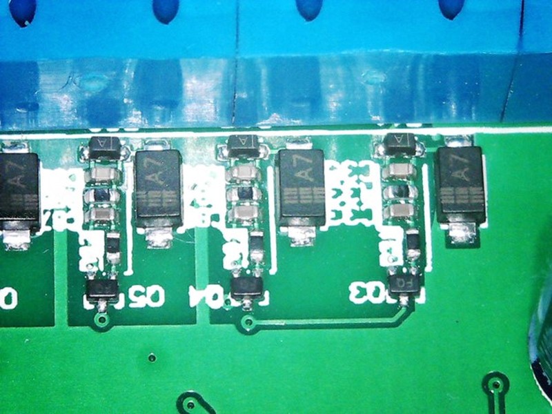
The back side is shown below:
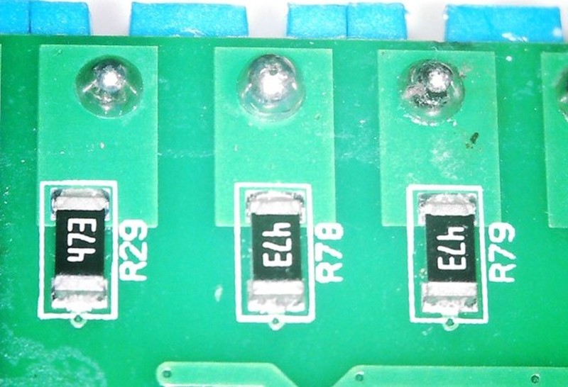
Using these pictures and a multimeter, we can create a simple schematic for one of the terminal outputs:
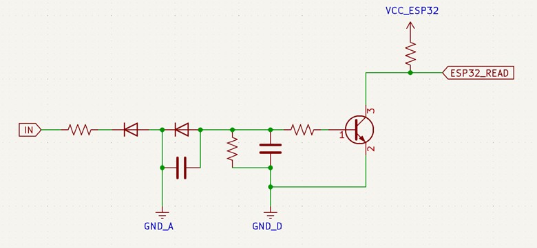
The circuit above allows the ESP32 to detect whether or not one of the external wall switches is open or closed.
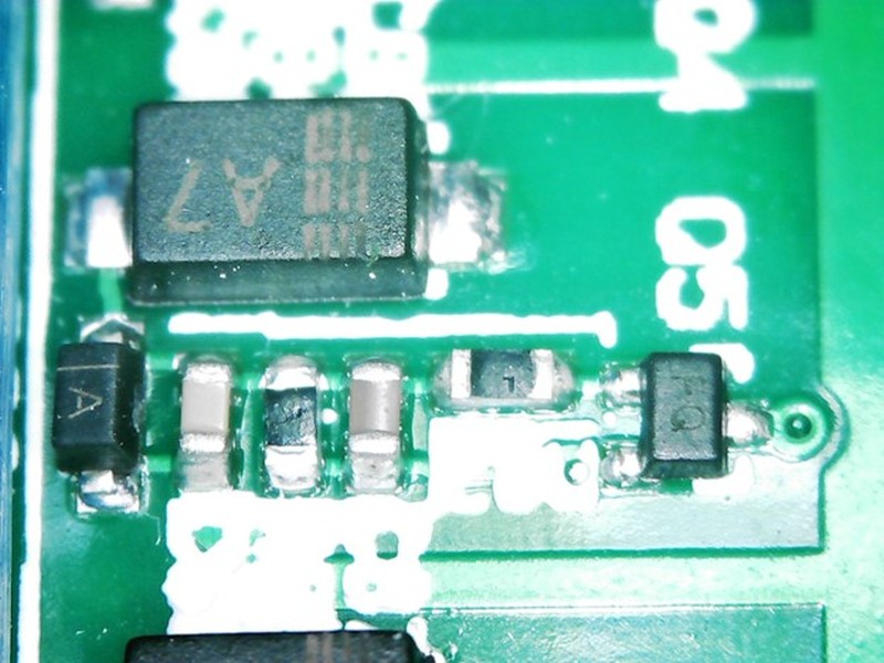
When a switch is closed then the “IN” pin will have the full AC voltage on it, which is converted by this circuit to a DC voltage which turns on the transistor, which then pulls the ESP32 GPIO pin low.
The “IN” global label is coming from the screw terminals and goes through a big resistor, which goes through two diodes to filter out the AC lines and a capacitor smooths the output.
There is only a half-bridge rectifier in this case, but a large enough capacitor along with a low pass filter (resistor in series with a capacitor connected to ground) smooths the output enough to turn the transistor on.
There are two separate ground planes: one for the AC circuit and one for the DC (or digital) circuit. These are labeled as “GND_A” and “GND_D” respectively.
This nifty little device has everything one needs to read wall switches and remotely toggle other devices around your home via WiFi.
Thanks to the powerful and highly-integrated ESP32, the design for this product isn’t all that complicated.
Final advice from John Teel:
Tearing apart products is a fantastic way to get insight into how they’re built, which is important to know if you plan to build a new product.
If you’ve not done so yet I highly encourage you to find products similar to your own, and (carefully) rip them apart.
However, as great as they are, product teardowns won’t help you understand the more abstract things that go into building a new electronic product, and making it a sales success.
To learn all that, I suggest the Hardware Academy.
The Academy is where you go to learn everything that’s needed to build a successful new electronic product that you can’t learn from ripping apart other products.
Learn more about the Hardware Academy.
—
This teardown was done and written by Matteo Cordray who is an electronics engineer that specializes in product teardowns and reverse engineering.
