
ATmega versus STM32: Which Microcontroller is Best for Your Application
This article compares the ATmega and STM32 microcontrollers so that you can choose the best one for your own tech product, by considering overall cost and system cost, as well as the upward migration path.

Comparing ATmega and STM32 microcontrollers is a bit like comparing apples and oranges. At a very general level, they are both fruits, in this case they are both microcontrollers. To take things a bit further, there are many variants of both.
A direct comparison of the Atmega and STM32 would not make much sense. However, there are cases where it makes more sense to choose one over the other.
This article will help you make the best choice for your particular tech product. Several, somewhat conflicting areas need to be considered when choosing a given microcontroller for an application.
Among them are overall cost, not just of the microcontroller itself, but the total system cost.
For example, if a microcontroller already has a built-in peripheral that removes the need for an external one, then that’s a much better way of approaching a design.
On the other hand, choosing an expensive microcontroller, with lots of extra peripherals that won’t be used, simply because it has one that is actually needed is not a wise choice.
Another thing to consider is the upward migration path of a given microcontroller family. It is important to consider the availability of tools, both hardware and software, and the ease of writing and debugging the application firmware.
ATmega Microcontrollers
The ATmega series of microcontrollers was originally made by Atmel which was then acquired by Microchip in early 2016. Microchip is the manufacturer of the PIC series of microcontrollers, which, in many ways is much closer to the AVR series than the STM32.
The ATmega is a relatively simple 8-bit Reduced Instruction Set Computer, or RISC, microcontroller with a Harvard architecture.
Figure 1 shows the internal block diagram of an ATmega328 as is found in the Arduino Uno. The separate instruction and data paths to the flash and SRAM of the Harvard architecture can clearly be seen in this block diagram.
Also evident in this block diagram is the regular, no fuss architecture.
Table 1 summarizes the main specs of the ATmega328. You can see that it is a relatively limited microcontroller and is not suitable for developing large, data intensive, applications.
In general, the main advantage of the ATmega family is they are quite easy to configure, without having to go through several layers of hardware abstraction. This is what makes it great for some classes of applications, for example controllers dedicated to doing certain control tasks.
However, as the range of Arduino-based projects out there amply demonstrates, there is a lot that can be accomplished by having this type of microcontroller as the main controller.
One additional area that needs to be mentioned is that the ATmega328, and other members of this family, is not cheap on a cost to performance basis. For example, as of this time, it lists for $2.08 at Digikey for a quantity of one.
However, Microchip seems to have realized this, and the latest ATmega 0-series is, in almost all areas, superior to the older ATmega microcontrollers, and are also cheaper.
For example, their ATmega3208 costs $1.03 in quantity of one. The architecture is somewhat different, but still quite close to, the older ATmega microcontrollers. So, unless there is a good reason to stick to the older ATmega microcontrollers, the newer 0-series should be considered.
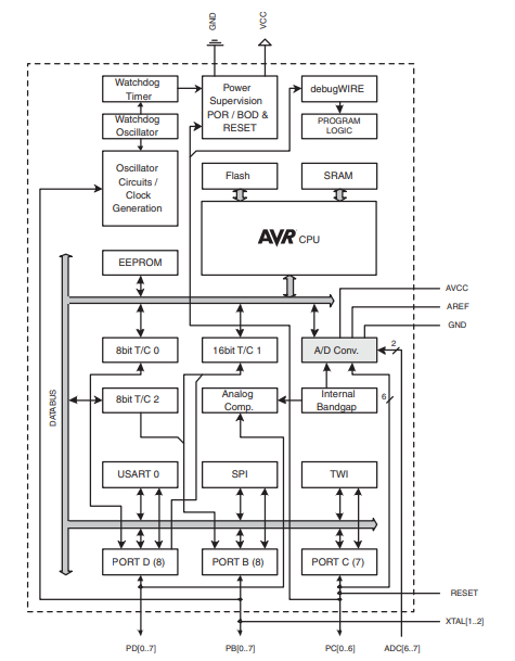
Figure 1 – Block diagram of an ATmega328 microcontroller
Table 1 – Major features of the ATmega328
STM32 Microcontrollers
The STM32 series of microcontrollers from ST Microelectronics is a popular, and very large, family of ARM-based 32-bit microcontrollers.
Being ARM-based means that the core of the microcontroller is one of the various ARM cores licensed from Advanced RISC Machines. In the case of the STM32, these can be Cortex M0/M0+, M3, M33, M4 or M7, either in single, or multiple, core configurations.
Being a very large family means that there are many variants to suit just about any embedded application. Figure 2 shows a high-level classification of the STM32 microcontroller line-up and their suggested application areas.
Within each one of these main microcontroller branches, there are many variants. In total, there are a few hundred microcontrollers in the STM32 family. So, choosing one can be quite an undertaking in itself.
Having chosen a suitable microcontroller, the next step is to actually understand its internal architecture so as to be able to successfully set it up for the intended application. While the STM32 microcontrollers are quite versatile and highly configurable, it is this very fact that makes them hard to initialize.
Figures 3 and 4 show typical internal architectures for STM32 microcontrollers based on Cortex M0 and Cortex M3 cores respectively.
As can be seen, there is quite a bit of difference between the two, and knowledge of one does not necessarily mean automatic knowledge of the other.
Adding to that is the fact that initialization involves not only the peripherals such as GPIOs, UARTs or SPIs, but the Cortex core itself. Without the proper tools, this endeavor can be very time-consuming and error-prone.
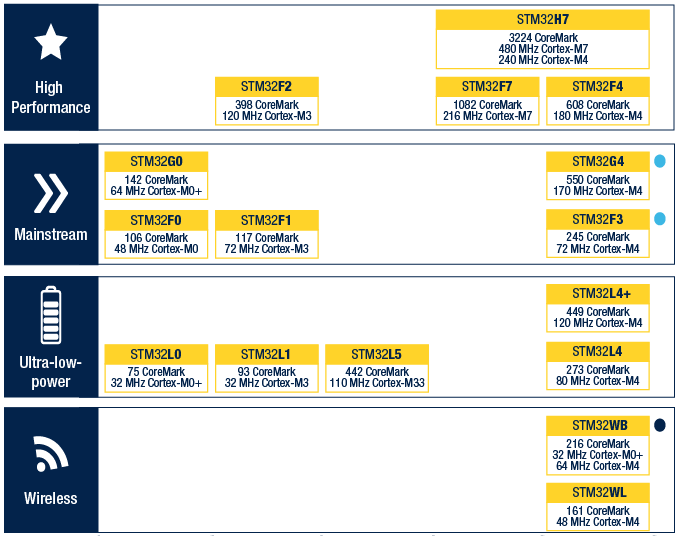
Figure 2 – STM32 family by application areas
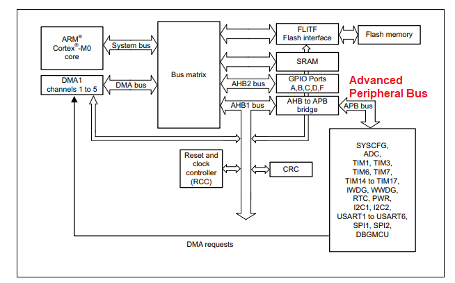
Figure 3 – Internal block diagram of a typical STM32 based on a Cortex M0 core
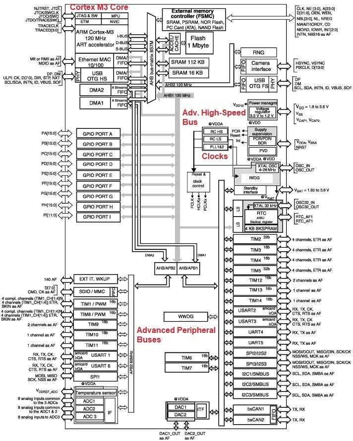
Figure 4 – Internal block diagram of a typical STM32 based on a Cortex M3 core
Despite all these complications, however, the STM32 microcontrollers have some major hardware advantages over the ATmega microcontrollers.
As an example, the STM32F030K6T6 has a Cortex-M0 core, and lists for $1.44 for a quantity of one at Digikey. Table 2 lists some of its main features. Compared to the ATmega328, it performs better in most respects at a lower piece price.
| Clock frequency (MHz) | 48 max. |
| Flash size (KB) | 32 |
| SRAM size (Bytes) | 4096 |
| EEPROM SIZE (Bytes) | None. |
| USART | 1 |
| SPI | 1 |
| I2C | 1 |
| Timers | 4 x 16-bit |
| ADC | 10 x 12-bit |
| GPIO | 26 (shared with other peripherals) |
| Internal ADC reference | Yes |
Table 2 – Major features of the STM32F030K6T6
As a final note for this section, it is worth emphasizing that the STM32 family has members that are simply out of reach of any ATmega microcontroller in performance and features.
Furthermore, STM32 microcontrollers usually have many variants in the same sub-family, allowing for easy migration should the application require it.
For example, the STM32F030K6T6 I just described has variants offering up to 256KB of flash, 32KB of SRAM, with two SPI and two I2C channels. Since the architecture is essentially the same, it is quite straightforward to port the existing code without much effort.
Software Development
Both the ATmega and the STM32 series of microcontrollers are well supported when it comes to developing application code.
For the ATmega series, the usual development environment is the AVR Studio IDE with GCC C/C++ compiler. The IDE can also be augmented with many useful extensions, and there are plenty of examples of fully functional code available.
Because the peripherals are fairly simple to configure, they are usually initialized by simply writing the configuration values to the appropriate registers.
One further aspect of ATmega code development that is worth mentioning is the Arduino angle. Many ATmega microcontrollers, such as the ATmega328, are used as the microcontroller in Arduino boards. It is quite possible to develop in Arduino, and load the compiled binary into the microcontroller.
Even if not using a directly compatible one, it is relatively easy to port an Arduino library, which is written mostly in C++, to another ATmega microcontroller. That way, it is possible to take advantage of the vast Arduino library base already out there.
To actually program the microcontroller, there is a large range of products with varying debug capabilities, including the AVR ICE MK II and some really inexpensive ones. It is also possible to build one, or use an Arduino as a device programmer from instructions that are available online.
Developing code for the STM32 is not as simple, or as straightforward, as for the ATmega case. While it is possible to write the initialization code from scratch, it is better to spend the time learning how to use STM32 CubeMx or CubeMxIDE.
The CubeMxIDE comes with its own compiler. CubeMX allows the use of another editor such as Eclipse, and an external compiler such as the excellent, but expensive, IAR compiler.
These tools, provided for free by ST Microelectronics, will save countless hours of frustration reading, and thoroughly understanding, the datasheet of the target microcontroller. These can run into well over a thousand pages.
These tools will automatically generate the initialization code for the target device. Even then, it need to at least understand the various options available for a given device.
So, it is fair to say that writing code for the STM32 is quite a bit more complicated than in the case of the ATmega.
For example, here is the initialization code, directly lifted from CubeMx, just to get an STM32F103C8T6 to be able to drive a couple of LEDs, for example.
/**
* @brief System Clock Configuration
* @retval None
*/
void SystemClock_Config(void)
{
RCC_OscInitTypeDef RCC_OscInitStruct = {0};
RCC_ClkInitTypeDef RCC_ClkInitStruct = {0};
/** Initializes the CPU, AHB and APB busses clocks
*/
RCC_OscInitStruct.OscillatorType = RCC_OSCILLATORTYPE_HSE;
RCC_OscInitStruct.HSEState = RCC_HSE_ON;
RCC_OscInitStruct.HSEPredivValue = RCC_HSE_PREDIV_DIV1;
RCC_OscInitStruct.HSIState = RCC_HSI_ON;
RCC_OscInitStruct.PLL.PLLState = RCC_PLL_ON;
RCC_OscInitStruct.PLL.PLLSource = RCC_PLLSOURCE_HSE;
RCC_OscInitStruct.PLL.PLLMUL = RCC_PLL_MUL9;
if (HAL_RCC_OscConfig(&RCC_OscInitStruct) != HAL_OK)
{
Error_Handler();
}
/** Initializes the CPU, AHB and APB busses clocks
*/
RCC_ClkInitStruct.ClockType = RCC_CLOCKTYPE_HCLK|RCC_CLOCKTYPE_SYSCLK
|RCC_CLOCKTYPE_PCLK1|RCC_CLOCKTYPE_PCLK2;
RCC_ClkInitStruct.SYSCLKSource = RCC_SYSCLKSOURCE_PLLCLK;
RCC_ClkInitStruct.AHBCLKDivider = RCC_SYSCLK_DIV1;
RCC_ClkInitStruct.APB1CLKDivider = RCC_HCLK_DIV2;
RCC_ClkInitStruct.APB2CLKDivider = RCC_HCLK_DIV1;
if (HAL_RCC_ClockConfig(&RCC_ClkInitStruct, FLASH_LATENCY_2) != HAL_OK)
{
Error_Handler();
}
}
/**
* @brief GPIO Initialization Function
* @param None
* @retval None
*/
static void MX_GPIO_Init(void)
{
GPIO_InitTypeDef GPIO_InitStruct = {0};
/* GPIO Ports Clock Enable */
__HAL_RCC_GPIOC_CLK_ENABLE();
__HAL_RCC_GPIOD_CLK_ENABLE();
/*Configure GPIO pin Output Level */
HAL_GPIO_WritePin(LED_GPIO_Port, LED_Pin, GPIO_PIN_RESET);
/*Configure GPIO pin : LED_Pin */
GPIO_InitStruct.Pin = LED_Pin;
GPIO_InitStruct.Mode = GPIO_MODE_OUTPUT_PP;
GPIO_InitStruct.Pull = GPIO_NOPULL;
GPIO_InitStruct.Speed = GPIO_SPEED_FREQ_HIGH;
HAL_GPIO_Init(LED_GPIO_Port, &GPIO_InitStruct);
}
Compare this to the equivalent code for the ATmega328 as given here, and the difference is quite obvious.
static void setup_IOPorts(void)
{
DDRB = SETUP_PBDDR;
PORTB = SETUP_PBINIT;
DDRC = SETUP_PCDDR;
PORTC = SETUP_PCINIT;
DDRD = SETUP_PDDDR;
PORTD = SETUP_PDINIT;
DIDR0 = SETUP_DIDR0;
}
Once the code is developed, downloading it to the device is fairly simple using a ST-Link V2 or ST-Link V3. There are also readily available, very inexpensive, ST-LinkV2 clones.
Also, because most STM32 have some kind of debug port, the device programmers can also serve as debuggers.
ATmega or STM32
While this section is about choosing between the ATmega and STM32 microcontrollers, most of it generally applies to 8-bit vs. 32-bit microcontrollers from a hardware perspective.
Here are some points to consider:
- In general, the quiescent current of the ATmega is lower than the STM microcontroller. This is especially true if the STM32 has lots of unused peripherals that cannot be turned off by the firmware. They just suck up power without doing anything useful in the user application. This, of course, might be a very important, or even prime, consideration.
- Most ATmega microcontrollers can run off 5V, whereas STM32, at most, have 5V tolerant inputs. The ATmega can happily run off three 1.5V series-connected batteries without any regulators, and can continue running until the batteries are fully depleted. For STM32s, 3.3V LDOs are needed, and they will go out of regulation when the battery voltage drops below the dropout limit of the LDO.
- Due to the larger feature size of their internal transistors, ATmegas withstand electrostatic discharge, or ESD, better than STM32s. In other words, their survivability rate to ESD is much higher.
- In some applications, the 5V logic is a big advantage when it comes to being immune to electrical noise.
- ATmegas generally have better drive capability compared to STM32s, which can minimize the use of external hardware drivers.
- Some of the peripherals of the ATmega microcontrollers are actually better than the equivalent STM32 ones, for example the ADCs.
- ATmegas have true EEPROM. Single bytes can be written or erased. STM32s can emulate EEPROM functionality in their Flash. While it can be made transparent to the user, it does involve another layer of firmware, and the number of erase cycles are not as good.
- In simple applications, all that is needed is just the ATmega microcontroller all by itself.
Conclusion
The STM32 can do anything that the ATmega can, and much more.
However, just as it makes more sense to drive to get groceries rather than take a helicopter, it is similarly more sensible to use an ATmega instead of a STM32 in some applications.
It is easier to develop applications for, and easier to use. In some applications, that is all that really matters.

Interesting comments on both
Atmega and STM32 microcontrollers as both are great
And flexible In diverse embedded system applications
There are 2 major problems :
1st Small chip size causes the
Internal comopents that dissipates
The most power to affect Vital
Circuits like the oscillator and
Converters with thermal shock
Causes with time to affect the connections between the components and reduces its service life .
(Few milliamps drawn from any
Pin or pins is enough to cause this to the chip)
2nd the esd shock and transient
Voltages when the circuit is powered up or an output circuit with high power is working and turning off normally in addition to smt
Used to manufacture the pcb
makes the components very close to each other as this causes
The mcu internal bypass diodes that absorbed those shocks over stressed (due to their very small size ) and shorts most of the time rather than getting open circuit .
As the embedded engineers and the circuit designers do some remedies to reduce those effects by
Using TVD indicators.. etc
And distribution of the smd components depends greatly on thier experience and how they understand the physical effects of those factors.
This can be noticed in commercial
Electronic appliances
Like a washing machine and
Smart TV that 70% of the malfunctions are in the mcu chip
Due to those 2 factors I mentioned above the other 30% due to weak
Design in power supply and
Thermal dissipation of the whole system to the outside ambient air .
Thank you any replies are welcomed
And special thanks to the author
Predictable designs owner.
Question: if I get the Atmel-ICE programmer/debugger for the Atmega328p or Attiny85 that I’m working on, can I also use this programmer/debugger for an STM32F103 or so?
In general, what kind of programmer/debuggers should I buy so that I can program several kind of microcontrollers?
Eventually, I’m also looking into dip my feet into something the like i.MX6, but I’m not sure what programmer/debugger I should buy for it.
“ATmega microcontrollers are actually better than the equivalent STM32 ones, for example the ADCs”
In what way are the Arduino ADC’s “better”?
What I find is the STM32 ADC’s have pretty low input impedances. This can be an issue if, for example, you are trying to read battery voltage through a resistive voltage divider. You have to pick pretty low values for the voltage divider resistors to prevent the ADC input impedance from affecting the voltage divider ratio. This can lead to excessive wasted current drain on the battery unless the voltage divider is switched on just for reading the battery voltage, and then switched off the rest of the time so that it is not constantly draining the battery.
I also find the readings to be a bit noisy, thus reducing the effective number of bits of the ADC. This could just be my setup though.
Have you checked with STM about these issues? One user mentions noise from USB https://community.st.com/s/question/0D50X00009XkfMDSAZ/stm32f4-adc-noise-with-increased-activity-in-usb-fs Other comments: Keep the wiring short, and make sure the resistor value matches the ADC input impedance. I’ve successfully used values between 2k and 10k. The higher the impedance and the longer the wires, the more susceptible to EMI. When the ADC samples the input voltage, a sample and hold capacitor is charged up. The signal current during this time can cause the observed ”noise” when the signal source is not of low impedance. Try increasing the sampling cycles. — In STM32F427?the ADC noise is horrible when the mcu access the sdram or fpga by fsmc at the same time. — Instead of the STM32 internal ADC, I used an ADS7822 12-bit SAR ADC from Burr-Brown. Ratsnested on the same board with filtering as described in my previous posts. Performance is excellent, < 1.5 bit noise. I conclude that in practice it is not possible to use the STM32 internal ADC at its advertised resolution, at least in packages where VREF+ and VREF- are inaccessible. — the most likelu cause is the return of your filter capacitor/the return of your input. I forgot to mention, ground is not ground. a wire is not a wire. — I would recommend to buffer with a fast and precise OP. — see STM application note AN2668 page 9! ”Improving STM32F101xx and STM32F103xx ADC resolution by oversampling”. STM has done a similar thing: 1.65V gave 2050count, min was 2034 max 2076. my conclusion is: never rely on a single AD result in your application if you need more than 8bit of precision. (PID control / if else decision etc) — My conclusion is this: there must be spurious charge shots out of the ADinputs. Quite rare, but if they hit the right timing, an attached condenser stores it, and corrupts the result. 1) With averaging / digital filtering you can eliminate these spurious results. Extreme values are very rare. 2) Do not use condensers on STM AD inputs. I have more than 20years experience with embedded measuring systems / analogue front ends. These effects are not there in 8051 derivates that I know, ATMEGA, PICs, also not on Stellaris Cortex M3 devices. — you, evidently believe the ground plane is ground IT IS NOT. make the input (or experimental resistors) connect no more than 0.5 cm from Agnd. your readings of 3V3 are correct, it jives with typical jitter on a supply rail. — I doubt that on 3 different types of eval boards the reason is always poor grounding. I rather suspect a poor silicon mask design on the F100 family. Maybe the ones with an external reference pin show better results. — Others seem to have come across this issue: ADC glitches (2nd page), they could actually see glitches with the scope. I had done more tests by changing the return path of the condenser directly to AVSS, instead 26counts, I achieved 20counts. Still way too… Read more »
https://community.st.com/s/question/0D53W00000cRpfLSAS/many-people-have-complained-about-noise-on-adc-inputs-maybe-to-do-with-impedance-has-this-be-rectified-on-any-version-or-family-of-the-stm32
i just got a possible solution:
“Have also a look at AN2834. Following the rules I get good results.”
Here it is. It’s a 60 page doc 😀
https://www.st.com/resource/en/application_note/cd00211314-how-to-get-the-best-adc-accuracy-in-stm32-microcontrollers-stmicroelectronics.pdf
solutions:
sample an analog input several times and take the average of the results by software.
—
In the STM32 microcontrollers with the ADC oversampling feature, the ADC hardware oversampling feature can be used for averaging. This feature simply performs the sum of a given number of ADC raw samples into one final sample. This final sample can then be right shifted to reduce the bit width caused by multiple ADC samples accumulation. All these operations (accumulation and right-bit shifting) are performed by hardware. The ADC hardware oversampling feature can be configured to process up to 1024 input samples
—
a relatively simple low-pass filter with a cutoff frequency fC just above the frequency range of interest will suffice to limit noise and aliasing. A sampling rate consistent with the highest frequency of interest will suffice, typically two to five times fC. Note: The R and C that form the external filter should have values that match the conditions described in Section 4.2.4 and Section 4.2.8.
—
Matching the ADC dynamic range to the maximum signal amplitude This method improves accuracy by a proper selection of the reference voltage or by using a preamplifier stage to obtain the maximum possible resolution using the full ADC output range.
Have you actually observed battery-drain? Some say the amount of drain from the ADC would take decades to drain your battery. Some solutions: a buffer cap, a FET, low bias current opamp, reduce the reading frequency, cut-off between samples, read the analogue input twice…
https://www.eevblog.com/forum/beginners/measuring-battery-voltage-without-consuming-current/
https://forum.arduino.cc/index.php?topic=413673.0
https://electronics.stackexchange.com/questions/64490/low-current-battery-monitoring
https://jeelabs.org/wp-content/uploads/2013/05/16/measuring-the-battery-without-draining-it/
https://forum.allaboutcircuits.com/threads/whats-the-best-way-to-measure-battery-voltage.120027/
Low-pass filter: https://medium.com/fiftythree-space-to-create/measuring-battery-voltage-is-simple-or-is-it-b54f12606a25
Of note:
“It’s a catch 22. The lower the sense current, the worse the linearity you create. The ADC will have an effective impedance, not in the real sense, but bad enough. This may be 100K or 1M. So if you have a 100K voltage divider, you’ll de-linearize the sense voltage range. If you don’t have a choice, then you’ll need to make up a LookUp table (or maths function) to correct the errors. If you use a BUFFER op-amp, as suggested, that’ll fix that problem, but now you have an Input offset to worry about (still quite doable). BUT – Unless you REALLY need to see the unloaded CELL voltage, then having a 0.mA, 1.0mA or GREATER load is no issue. You’re only applying it during the “read” cycle anyway. And even left on, it’s a TINY percentage of the CELLs energy storage. If you need the know the total energy precisely, then just add the ~1mA in firmware/software. When testing batteries, designers often have an output to drive a programmable (set) load, to see how the CELL behaves under load, as the CELL will have an internal leakage current ANYWAY. For NiMH (non LSD) this can be quite (relatively) high !!”
I have a good experience of developing with STM32.
I’m using Arduino IDE and it’s as simple as developing with an atmega µc.
All the major libs are also supported by the STM32 core.
In my current project, I’m driving an OLED screen in addition to controlling a radio chip (si4735) and storing data in an external eeprom.
Sending code to the STM32F103 is very easy thanks to the ST-Link v2 device (or clone), as it’s basically supported out of the box by the stm32 core.
So for me, I see all the advantages:
In the con’s, there’s no internal EEPROM… but external eeprom’s are dirt cheap and easy to connect to.
Stéphane
Thanks for sharing this Stephane!
Hi.How are you?
I have one question.
When we choose NewProject->Device Selection after that i don’t know whichone choose for stm32f103c8t6 at Device Selection in CodeVisionAVR app.Can you help me?
Because at CodeVisionAVR ->Device Selection is about ATmega or ATtiny or ATxmega and
doesn’t have stm32f103c8t6 and i don’t know what shoud be done.
can i use Arduino Atmega3256 to load code on stm32
it was better to compare with more recent series like the AVR DA family?
I had a good experience working with Platformio+mbed and Platformio+STM32duino on the STM32 platform. Which is as easy to set up on an Arduino Uno in the Arduino IDE. This very is very much in favour of the STM32, as this reduces the barrier of entry a lot compared to the ATmega.
Just grab a Nucleo board and you have the ease of Arduino and the power of debugging over ST-link.
While we maintain a good number of projects on Atmel processors, we have stopped using the AT Mega series of controllers for new projects a while ago. Microchip has discontinued some lines and the future of the series – other than the chips used in Arduino – remains uncertain. There probably is still a place for say an AT Tiny in a low cost basic performance application, but that could easily be an STM8. Anything else requiring more performance or periphery goes onto STM32. So aside from cost, performance and everything else mentioned, the STM lines simply have ‘more life left’ in them for use in commercial and industrial applications, and that is important for our clients.
Nice article but I think you underemphasized something. I’m not familiar with the ATmega microcontrollers other than dabbling with Arduino for a brief time. But one big difference between Arduino and STM is debugging and I believe this needs more emphasis. As far as I can tell, it is impossible to set breakpoints or examine memory using an Arduino, yet full hardware debuggers are built into the STM microcontrollers (and TI). With an Arduino you are forced to put print statements in your code. This is awful. Debugging is time consuming enough without having to resort to primitive techniques due to limitations of the microcontroller / IDE. To me, this is an enormous problem with Arduino (and maybe ARmega) and I believe you should consider posting another discussion about the relative advantages of the vendors when it comes to debugging.
You are correct in stating that Arduino does not support debugging beyond some Serial.print and maybe toggling some digital IO’s. However, there are debuggers such as STK600 and ATMEL ICE Mk II. However, they are expensive. There is also an emulator in AVR Studio that works quite well. Even though you could load extensions in AVR studio that allow developing Arduino code in AVR Studio, debugging that can be somewhat complicated. For example, there is a lot going on behind something as simple as Serial.begin that Arduino does in the background. This is the price one pays for the convenience. Ins=uch cases, it is best just to “Skip Over” when single stepping.
As for the STM series, yes the debugger is built right in, and even the cheap ST-Link clones are quite powerful “debuggers”.
Should be mentioned that the kByte of Flash on an STM32 (ARM architecture) is worth less than the same amount of Flash on an ATmega (AVR Architecture), the latter being worth 1.5 to 2 times the value of the former.
This is due to the fact that the ARM (compressed) thumb code requires 16 Bits per instruction while the AVR gets away with 8 Bits. There are certainly some wars of belief on that, but that’s how things are. Plus the fact that an ARM running from thumb code looses performance (aka “speed”). While an ARM running from 32-Bit code requires significantly more Flash to just do the same.
I recently benchmarked an ARM M0(+) vs. a PIC16 in terms of pricing (no arguments about the differences in execution speed please!) – ending up with a price advantage for the PIC16 of about 50 %. The same will hold true once the AVR architecture is completely adopted by Microchip and the AVR cores come with the latest CIP peripherals. Then even a slower 8-Bitter might outcompete an ARM core on quite a number of applications.
P.S.: And real-time performance of ARM cores is just awful. No comparison to the short-latency performance of recent 8-Bitters.
These remarks are true in some cases, but counter-cases can be made as well. For example, if the application is very maths-heavy with 32-bit numbers all around, then any 8-Bitter would be at a substantial disadvantage, even if it has a hardware multiplier. Again, if the application is large, or is data-intensive, the larger address and data space of the STM32s would allow applications that are simply out of reach for 8-Bitters. Also, granted that some of the lower-end STM32s run Thumb-2 instruction sets, but some of the high- end STM32s at full32-bits.
In the end, it is a bit like comparing using a desktop PC to send some characters over a UART, and using an 8-Bitter to do the same. Even discounting the USB to UART converter that will most certainly be needed, the code required for the PC to do that is going to be much, much than that from a 8-Bitter. However, the PC can be doing that while at the same time downloading a movie while at the same time you are surfing the net.
Nice article. Would be good if you could show some more examples than just setting it up to blink an LED with the STM32CubeIDE. Hope to see such examples soon.
Keep up the good work. Cheers.
Thanks for the feedback Jay, much appreciated!
Here is a link of how to set up blink using STMCube: https://wiki.st.com/stm32mcu/wiki/STM32StepByStep:Step2_Blink_LED
Using CubeMx involves quite a few steps that must be undertaken whether it’s for something as simple as a blink program, or something much more involved. You would need to make a project, then select your target MCU. After that, you have to decide which of the MCU pins to use, and configure them accordingly. Then you need to configure clock source: internal, external, pre-divisor. Then, you generate the code. There will be a lot of pre-generated code to configure the GPIO’s and clock. You can, for the most part ignore these, and just assume that the generated initialization code implements your selection.
After all that, you can then work on your application code. For something such as a blink program, you will not be installing any libraries. However, you will still have to use some HAL functions. There are HAL functions to provide delays and for toggling GPIO pins that you can use.
The good thing is that, as mentioned, these steps are carried out whether it’s some simple application or a large application. The other good thing is you get complete control of the MCU. For instance, you can set the output level, or max. speed of GPIO pins to save power, or decide whether a GPIO pin has push-pull output or no. Arduino, for example, just lets you have it one way by default. The bad thing is everything is configurable, and has to be configured prior to running even the simplest of code.
Just as an aside, it is possible to change the defaults used by Arduino for STM32 because it is possible to call HAL functions from Arduino. In such a case, the code will be larger since you are essentially adding more code to override what Arduino already did. Sometimes it is absolutely necessary. For example, Arduino provides no native way to reset the MCU by FW. Yet, by going even lower than HAL to the CMSIS layer, you can actually do this from your Arduino code.