
How to Transition an Arduino Shield to a Custom Board Design
In this article you will discover the process of transitioning Arduino shields to your own custom board for mass production. Two specific examples of Arduino shields are covered.
Any hardware product entering a phase of manufacturing-at-scale will, in all likelihood, need to be ported from its prototype form into a custom PCB.
The prototype being converted may take the form of a breadboard/protoboard with an intricate circuit.
One of the most common forms a prototype will take is an Arduino development board with one or more shield attachments.
These shields expand the functionality of the microcontroller carrier board by providing access to external ICs or sensors.
These can include anything from external storage to motor drivers to GPIO expansion.
They will generally work by physically connecting to all of the host board’s pins, but only make use of a few of them and pass on the rest so that further connections can be made.
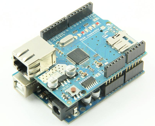
Figure 1 – An Arduino UNO dev board with an Ethernet shield attached.
In this guide, we will discuss the process for taking an assembled, functioning Arduino + shield combination and turning it into a custom board, complete with examples using popular shields on the market.
General Guidelines
First we will cover some general considerations when beginning the design.
As discussed already, shields will reserve some of the pins on the dev board for themselves and pass the rest through.
Thus, a critical first step is ensuring that you are fully aware of which I/O pins have been reserved by the shield for its functionality.
For a flash memory shield, for example, it is likely that it has reserved SPI pins on the Arduino for its functionality, and possibly a few GPIO for other purposes.
As many shields come with associated “drag-and-drop” libraries that a prototype may have made use of, it is possible that some designers of a product utilizing a shield may not have had to perform this step initially.
If you have not already done so, take the time to tabulate all of the pins being used by the shield (or shields) that make up your prototype stackup and associate them with pins on the microcontroller.
For example, pin D9 on the Arduino UNO would be pin PB1 on the microcontroller itself, which would be the nomenclature you will be working with when designing the schematic.
It is a good idea to start from a prepared schematic of a custom PCB for the microcontroller on its own, and add the elements from the shields afterwards.
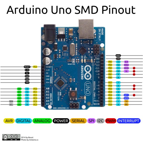
Figure 2 – A diagram of the Arduino UNO R3 pinout
The next general element to sort out is your power. This should be fairly easy to work out without delving into the shields yet, since you must have already provided the power supply to get a working prototype!
The easiest cases are those in which the shield is powered entirely via the microcontroller.
In other words, the only external source you have to provide is that going to the Arduino itself, because then you know that the bare minimum power your board needs can be sourced from a single voltage rail.
In the event that your board did require additional external power (this is most common for motor drivers) keep in mind that you will have to provide that other power source to your board as well.
Depending on the specific needs of the application, this could be as simple as remembering to include another connector on the board, or as complex as adding an entire voltage regulator to the design.
Example: Arduino Motor Shield
At this point you should have a schematic with an Arduino microcontroller and your power source needs are met, with whatever solution that ended up being.
Now is the part where the actual shield hardware starts getting ported to the schematic. To illustrate this process, I will use a couple different shields.
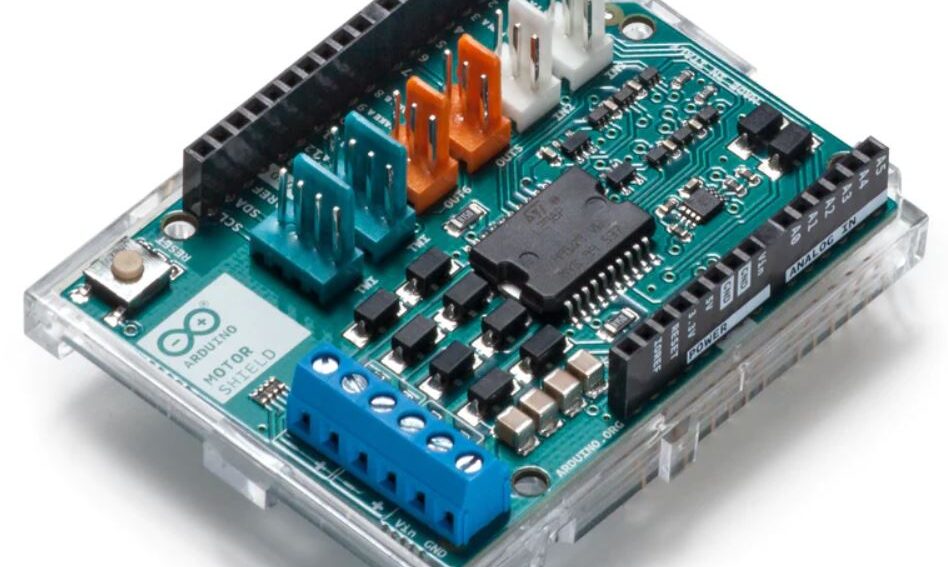
The first is the official Arduino Motor Shield Rev3, which is designed to be mounted on the Arduino UNO.
This shield can drive DC or stepper motors, and is an example of a shield with an external power supply required.
There are two routes that can be taken when porting a shield like this into a custom schematic.
The first is more brute force and involved, but may be required if your design has unique cost or space requirements, in which case you will want to strip some unused functionality from the shield.
With this route, you take note of the central IC that the shield is built around. In this case, that IC is the L298 motor driver from ST.
We would start with the datasheet for the chip, and follow that to gain a deeper understanding of the various pins available on the package and what external components are required to make it work.
With this process we are essentially using the shield as an inspiration to build a custom circuit from the ground up.
For shields that do not actually provide design files, this process is mandatory, and depending on the constraints of the project it may be recommended even if design files are present.
However, in the event that the vendor has provided design files they should still be used regardless.
No matter how experienced an engineer is at designing the circuit, nothing beats a design that has been proven to work well for the application as demonstrated by the shield in the prototype.
The Motor Shield is open-source hardware and thus provides design files as well as a PDF schematic of the shield, pictured in Figure 3.
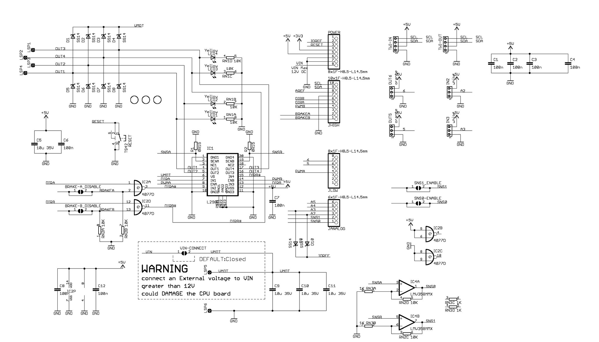
Figure 3 – The schematic for the motor driver shield provided by Arduino
The easiest and safest course of action (i.e. the one that is least design-intensive) is to simply copy the schematic, using the design files or documents as a reference, as a block into your existing schematic with the Arduino.
Then, break the connections on the shield that go to pin headers, and instead route traces directly to where they would have gone had the shields been joined.
In the above schematic for the shield, the GPIO breakout pins can clearly be seen in the middle.
When doing this, also ensure that power and ground are correctly connected to the power and ground you have already provided in your custom schematic.
This is particularly important if you are copying directly from the design files in a literal cut-and-paste fashion, since different schematics may use different symbols for power and ground.
You may have to convert the third-party GND symbols to your own, or vice versa.
Any pins that would have gone to pin headers, but you did not use in the prototype, can be safely left floating.
This is a good time to double-check the pin table that was made at the beginning of the design process, to ensure nothing is overlooked.
This is another case in which pre-made libraries can come back to bite you – consider the example of this motor driver having a SLEEP pin that is active low, so that it must be pulled high to keep the driver active.
A pre-made library may come with some generic Motor_Init() function that raises that pin high in the background, and it is likely that many applications would never use that pin to put the device in sleep mode.
If it is left floating inadvertently in the custom PCB, this would obviously cause problems since the pin is no longer pulled high.
The lesson here is that checking just the user-written code to determine the used pins is not necessarily sufficient.
Consult whatever documentation is available for both the shield itself and any third-party codebases that were pulled in to support it.
There is no reason to completely remove the pin headers from a custom design, and indeed it can be a good idea to leave a few on.
But considering that size and cost may be a factor in the custom board design, do keep in mind they can be removed safely as long as the necessary connections are made.
Another common source of bulk on shields like this one that can be removed are jumpers. Consider this design note on the product page for the motor driver:
“If your motor requires more than 9V we recommend that you separate the power lines of the shield and the Arduino board on which the shield is mounted. This is possible by cutting the “Vin Connect” jumper placed on the back side of the shield.”
It is highly likely that you will know the power requirements of your motor before the board is designed.
So, instead of leaving that “Vin Connect” jumper on the board (see underneath the main IC on the schematic in Figure 3), it can simply be removed and the proper connection made directly in its place.
This can be done for any jumper on the board, as well as any extraneous breakouts.
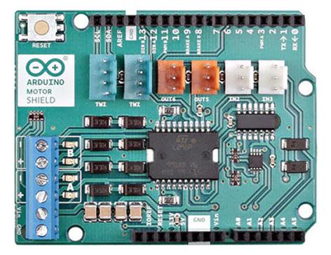
Figure 4 – The Arduino Motor Shield Rev3
Note the large number of small connectors on top of the shield in Figure 4, noting that a specific application may only use one or two of those.
Finally, note that there should already be a reset button on the microcontroller schematic, so the one visible at the top left on the shield image can just be removed as well.
There are several other opportunities for stripping down the shield, but the ones just listed are some of the low-hanging fruit that help the board truly become tailored to the application and reduce unnecessary cost and size.
For high-power boards like this one especially, also take careful note of how the PCB itself is routed – it is not always sufficient to just copy the schematic, roughly finish the layout, and call it a day.
Note the thickness and length of critical traces like power and motor outputs, and also refer to the datasheet for the chip for this.
Most ICs with critical power or thermal requirements will have PCB design guidelines that you can reference along with the design files themselves.
On this shield, for example, note the placement of the diodes to the left of the motor driver IC as well as the thickness of the traces surrounding them.
Opening the provided design files in EAGLE will help illuminate specifically what traces these are and where else they go on the board.
Example: AdaFruit Data Logging Shield
Following that high-powered example, let’s take a look at another shield with less strenuous power and thermal qualities: this Adafruit data logging shield for the Arduino UNO.
This particular shield contains an SD card slot, an RTC, and a coin cell battery for long-term timekeeping.
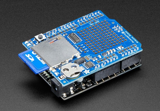
Figure 5 – The data logging Arduino shield by Adafruit
A look at the schematic shows that this one is much simpler and easier to follow than the motor shield, and helpfully includes the Arduino itself as a schematic item to aid in viewing the connections from the shield to the dev board.
For designs that are fairly simple like this one, there are fewer and fewer reasons to not copy the design directly with little to no modifications – with only a dozen or two components in total, there is little room for improvement or stripping down.
A look at all of the empty space on the shield corroborates this fact. However, this does not mean the schematic can go without modifications.
There are still a couple jumpers on here that can be removed along with the pin headers, and your application may not need the coin cell battery at all.
Note that the battery can be simply removed without replacement for the power source, since this RTC chip (along with most like it) have two power supply inputs, VDD and VBAT, the latter of which is only used when the former is not available.
Additionally, do not forget the logic level converter on the bottom left, which is required for interfacing with the SD card reader.
Conclusion
Hopefully this article and the couple of examples I have shown prove to be beneficial in turning your Arduino shield-based prototype into a scalable product.
With the benefit of open-source hardware designs, the work involved can potentially be very little if your design has few cost and size requirements.
But keep in mind that you can always refer to lower-level information like chip datasheets for assistance in making modifications to the shield design.
Be sure to check out these other articles about how to transition an Arduino prototype to a custom design that can be mass produced:
From Arduino (Uno) Prototype to Mass Production
From an Arduino Mega Prototype to a Custom PCB
