
From an Arduino Mega Prototype to a Custom PCB
Discover the steps required to transition both the hardware and firmware from an Arduino Mega based protype to a fully custom PCB that can be mass produced.

It’s no surprise that for larger projects with many peripherals or heavy GPIO requirements, the Arduino Mega is a popular choice for an electronics device.
Since it is one of the premiere Arduino platform dev boards and from the same microcontroller family as the even more ubiquitous UNO, transitioning to it from other Arduino projects is a breeze.
Learning how to work with the Mega is no different than working with smaller Arduino boards.
However, as with all dev board prototypes, there comes a time when the breadboard project needs to be taken to a scalable, manufacturable product.
This article aims to cover both the critical hardware and firmware adjustments that need to be made when transitioning your Mega-based prototype into its own full-fledged product.
Arduino Mega Hardware
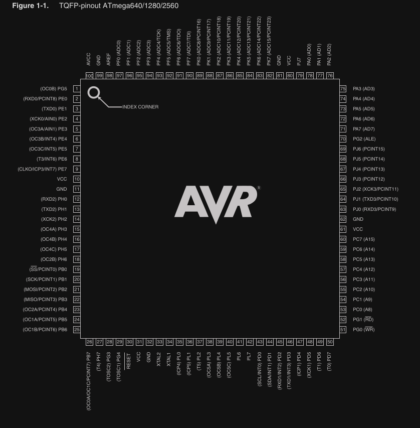
Starting with hardware, the Arduino Mega is based on the Atmega2560 microcontroller. In the iteration that is found on the Mega board, the microcontroller comes in a standard TQFP 100-pin package.
There are 54 standard GPIO available and a variety of peripherals including dedicated PWM channels, the typical serial interfaces like SPI and UART, and more.
It is a 5V microcontroller like the Uno, so your first step when transitioning this chip to a custom PCB should be to ensure that your board provides a 5V source to power the board.
Note that the microcontroller provides an AREF pin on pin 98 for the package above. This can be left floating or shorted with a capacitor to ground, since the microcontroller can source its own reference.
But if your application has particularly stringent analog performance requirements it is recommended to use a dedicated voltage reference chip.
This is an IC designed to provide a very stable, noise-free DC voltage source that does not need to provide very much current.
This reference can and should be separate from the primary power supply, even if the voltages are the same. If your ADC requirements are not very strict, you can ignore this and simply tie the pin to a capacitor.
When it comes to the rest of the schematic, there is generally no reason to not reference the schematics for the official Arduino development board.
For the Mega specifically, the schematic is here.
USB
When first looking at the schematic what will stand out is that there seems to be two microcontrollers, a larger one on the left and a smaller one on the right.
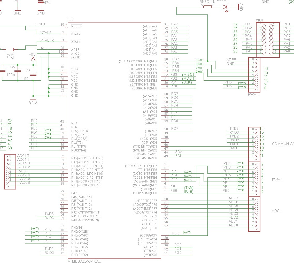
Figure 1- Schematic diagram for Atmega2560 core microcontroller circuit
The larger microcontroller is, of course, the Mega.
The smaller one, the Atmega8U2-MU, plays the role of USB-to-serial conversion, since the Atmega2560 does not have built-in USB functionality, only UART.
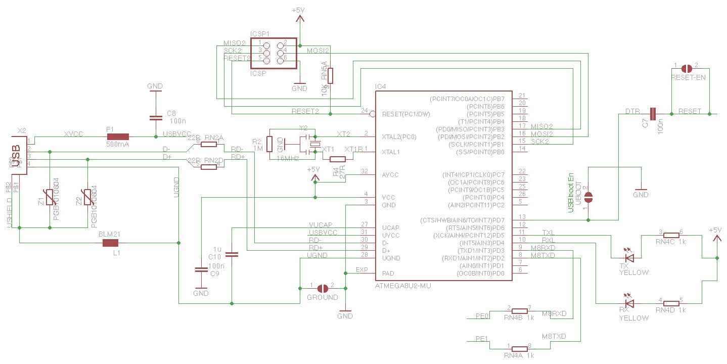
Figure 2 – Schematic diagram for Atmega8U2-MU USB-to-UART circuit
This brings us to a critical decision point in the hardware designing process; whether or not to retain USB functionality on the new manufacturable design.
The main argument against doing something like this is that if you are not using the USB functionality for something critical to your application (your device does not need to hook up to a PC for example), then including built-in USB connectivity is unnecessary.
It adds additional cost for the extra microcontroller and all of its required external components.
It also demands that a portion of the board edge must be clear for the USB port itself, which can be an issue in size-critical applications.
Programming interface (USB vs ICSP)
If you are freshly coming from dev-board Arduino programming, you may now be wondering how to program the board if there is no USB port.
After all, with the development board you just plug the computer into the USB port and upload code that way.
However, there is an alternate way to upload code to an Arduino board in the form of the 6-pin header labeled ‘ICSP’ on the dev board, with the same name in the schematic.
ICSP, or In-Circuit Serial Programming, is an SPI-style interface that requires an external programmer to upload code to the microcontroller. It is a lower-level way to upload code to an AVR microcontroller compared to USB.
ICSP is used by obtaining an external programmer like this one, and indicating in the Arduino IDE under Tools→Programmer what you are using. For this programmer, you would select AVR ISP.
From there you can write and upload Arduino code to the board as normal, as long as the programmer is connected on one end to your PC and the other end to the Arduino ICSP header.
ICSP is the ‘official’ way to upload code to the Atmega2560, so how does USB work?
This is accomplished via a bootloader, or a tiny program that controls the startup behavior of the firmware.
When this bootloader is ‘burned’ to a new Atmega2560 microcontroller using the ICSP, it essentially gains the ability to watch for and accept code uploads over another interface as well.
In the case of the Mega dev board, this interface is serial UART with an intermediary USB-to-UART converter to allow code uploads to be initiated and performed over USB.
The bootloader is designed to remain no matter what code is flashed over USB. It is easily burned using an ICSP programmer, by selecting the option Tools→Burn Bootloader in the Arduino IDE.
Once this is done, code upload is possible via serial as normal.
For a new custom PCB with an Atmega2560, at least the first code upload must be done with an ICSP programmer, since chips will not come from the factory with a bootloader.
Subsequent uploads may be done with an ICSP programmer as well, which is fully supported with the Arduino IDE.
There is not an explicit need to keep the USB port when transitioning to mass production
Should you wish to keep using the USB port for code uploads (essentially a ‘vanilla’ Arduino experience), simply burn the bootloader once using the ICSP programmer and then continue making code uploads over USB.
The USB-to-serial communication does not need to be done with a separate Arduino microcontroller as it appears on the Mega schematic.
There are a variety of dedicated ICs out there, most notably from FTDI, that perform UART-to-USB translation.
As long as your design utilizes the same TX/RX serial pins as the Mega dev board does (PE0 and PE0), your implementation should function largely the same.
Additional circuits
When it comes to the rest of the schematic, you can certainly just copy the circuit and IC item-by-item.
But, there are definitely a few parts you will want to strip away for a real product, most notably the pin header breakouts for all the GPIO.
Just leave the unused ones floating and only break out a small amount for debugging/emergency purposes.
Also note that the AREF pin in this schematic was left floating, but as mentioned above this can be tied to a stable voltage reference for precision analog purposes.
Finally, the Mega schematic depicts a voltage regulation block in the upper left corner that may be redundant in a custom board if you have already implemented a sufficient power solution.
The primary components that you must absolutely take from the Mega schematic are the directly connected capacitors and the clock, as well as the reset pin circuitry.
Everything else is optional or is likely to be implemented uniquely by your team.
Keep in mind the maximum current ratings for both Vcc and GND pins of 200mA, and the maximum DC current per I/O pin of 40.0mA.
Depending on how exposed or critical your design is, you may wish to incorporate some overcurrent and/or overvoltage protection onto your board in order to keep your microcontroller safe.
Integrating external functions
Another item that is often overlooked in the custom PCB transition is the integration of external components like sensors.
Many of these may have previously been integrated into your project as breakout boards, and these boards may contain extra circuitry that provides logic-level conversion, protection, etc.
Always review the schematics for these breakout boards where possible.
You can also consult the datasheet for the bare chip, to ensure that in the transition to a custom board you will not be breaking compatibility with the microcontroller.
It is understandably common to focus on the processor, but a missing set of transistors can make the difference between an I2C connection working or failing because the sensor had a different logic level than the Arduino.
Or even worse, a sensor or the microcontroller gets damaged due to an incorrect logic level voltage.
Arduino Firmware Migration
So now let’s say that you have constructed a custom board with an installed Arduino Mega, and you have gone with one of the options above for uploading code to the device.
What is going to change now when uploading the prototype firmware, in order to adapt to the new board?
In a perfect world, where your electrical specs exactly match the dev board’s as well as your prototype setup, there may be no changes required.
But frequently, when switching to a custom design, concerns may arise that require firmware tweaks to compensate.
ICSP programming
The most obvious change will be required if the USB port is no longer used to upload code in favor of the ICSP programmer.
In this case, a codebase that makes liberal use of calls to Serial_println()will require adjustments, since the ‘default’ serial port (the same UART→USB pipeline used for programming) is no longer available.
This issue can be addressed in the hardware too, and has a few solutions:
1. Break out the UART interface to header pins, and use an external FTDI adapter like this one to read back those print statements when testing code.
If you use the same UART interface that is connected to the USB ports on the stock Mega, there shouldn’t be any firmware changes required.
2. Print to a separate UART interface. This requires a relatively small firmware change of simply adjusting the port that the Serial print library uses to write to.
Startup timing issues
Another change is more general and can apply to any microcontroller that is ported to a custom board: startup timing.
A common occurrence that can be missed on dev boards is that different capacitance values and different PCB layouts can cause the timing of startup events to change.
For example, if your custom power implementation has quite a large capacitance compared to the Mega dev board, or your PCB has very long traces coming off of the microcontroller GPIO pins.
This may cause cases in which the microcontroller takes longer to start up or a GPIO signal takes longer to stabilize.
In short, never assume that signals will retain their speed and integrity when switching to a custom board, and especially test code that runs right on startup to ensure it still runs properly.
One example of this is a microcontroller that reads the state of two GPIO pins that are pulled up to 5V (think a hardware ID) on startup.
If there is too much power supply capacitance, the microcontroller may be able to start up and begin executing code before the GPIO signals stabilize.
This may cause a bad reading of the pins, so you may need to add a startup delay to compensate for this extra stabilization time.
This is just one example of many of how subtle hardware changes can require steps to be taken in the firmware to correct.
Hidden features for external components
Another software change that may be required ties into the external component discussion from above.
When placing a part into a schematic when having previously just used the breakout board, you may note that there are interfaces available to the chip that were not utilized in your prototype.
Common examples of this may be an audio module having a dedicated reset button that was shorted out on a breakout board.
But now you have the option of tying it to your microcontroller GPIO and then issuing a reset via software.
Another example is perhaps a fault pin that is now available on a motor driver chip that wasn’t accessible on the dev board.
With the flexibility of a custom PCB comes new opportunities to interface with your peripherals, and this requires changes or considerations with the software as well as the hardware.
Final Advice
There are a lot of choices to make when switching to a custom PCB from an Arduino Mega.
But, by sticking close to reference schematics and carefully considering external components, it is possible to make the transition with very few changes to your firmware.
Using the same microcontroller as your Arduino is always the easiest way to transition to a custom PCB.
But, it probably is not the most cost effective option.
Before you lock yourself into a specific microcontroller, you should review the costs compared to alternative microcontrollers if you plan to bring your product to market.
In most cases there will be cheaper microcontrollers available with equivalent or better performance and features.
However, then your transition to custom PCB becomes more complex from both a hardware and firmware development standpoint.
Written by Brandon Alba with additional advice added by John Teel
