
How to Create a Proof-of-Concept (POC) Prototype for an IoT Device Using the ESP32
You will learn how to build an early prototype for a new IoT product based on the popular ESP32 microcontroller series which is also a great solution for mass production.
The Internet of Things (IoT) is far past being a new wave, and it is now incredibly common for new hardware products to have wireless connectivity, with Bluetooth and WiFi being the two most popular protocols.
With FCC licensing and the various electrical intricacies of wireless technologies, it can be daunting for a new company or team to begin the process of developing a new internet-enabled device.
The antenna, wireless circuitry, and microcontroller can each bring their own unique challenges to the table.
Developing or sourcing each of these individually and then bringing them together into a cohesive, working device is a challenge.
Luckily, there are a variety of microcontrollers with built-in wireless that are available both as a SoC (System-on-Chip) or as a SoM (System-on-Module).
These usually come with an integrated, licensed antenna out of the box, in form factors that are friendly to prototypes and finished products alike.
Introduction to the ESP32 Wireless Microcontroller
One such SoC is the ESP32, which is a popular chip developed by the Chinese company Espressif that supports both WiFi and Bluetooth.
The ESP32 is a very affordable solution especially considering its high level of performance and extensive features.
It sports a powerful single- or dual-core CPU with a high 240MHz clock speed, and 448kB of read-only memory as well as 520kB of SRAM.
In addition to supporting WiFi and Bluetooth, its kit includes the array of peripherals that those with embedded systems experience will be used to.
This includes various timers like RTC, DAC/ADC, popular serial interfaces like UART, I2C, and SPI (supports quad SPI for external flash memory – think photo or video storage!) and even Ethernet, PWM, and Hall sensor support.
Its potential applications as directly stated by the manufacturer range from video streaming to wearable electronics and robotics.
This SoC was designed from the ground up to be versatile, and its popularity means there is a wealth of online resources to learn from as you adapt this device to your application.
There are a few different models of this SoC to choose from, most succinctly outlined by the following excerpt from the datasheet:
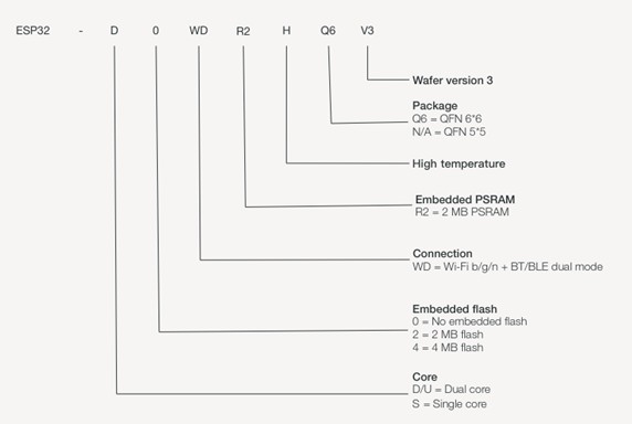
Figure 1: Part numbering scheme for ESP32 microcontrollers
The specific model your application requires may or may not be important.
For example, users with high computational requirements like a complex, multithreaded application or video streaming will want to opt for the dual-core processor.
Or for instance, applications with data logging requirements may want the embedded flash and/or PSRAM.
From POC Prototype to Mass Production
One of the reasons why the ESP32 microcontrollers are so good for prototyping is the manufacturer not only manufactures the bare chips, but also produces ready-to-use modules based around these exact microcontrollers.
There are three stages of development all possible with the ESP32 platform which drastically simplifies the transition from POC to mass production. These stages include:
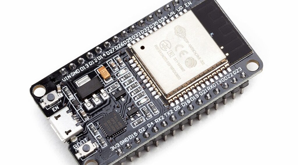
Stage #1 – Develop the early POC prototype using a development board incorporating an ESP32 module (see figure 2 below). This stage requires no FCC certification.
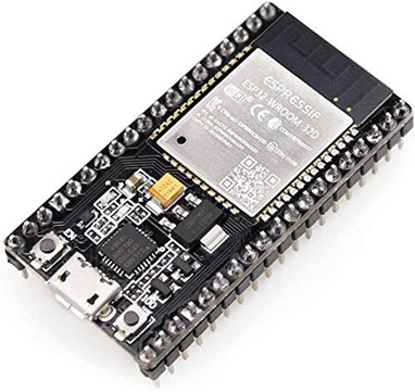
Figure 2: ESP32 module on a development board
Stage #2 – Design your own custom PCB and solder an ESP32 module (see figure 3 below) directly onto your custom board.
This stage requires limited FCC certification. Since the wireless portion of your design is handled by the pre-certified module, the FCC will classify your end-product as a “non-intentional radiator.”
Non-intentional radiator certification is much cheaper and simpler to obtain than full “intentional radiator” certification.
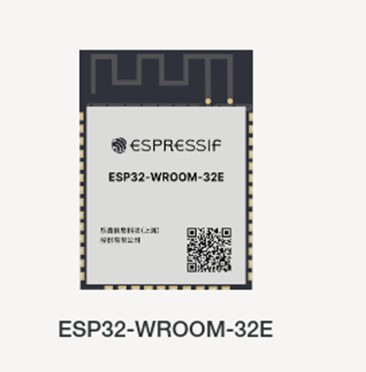
Figure 3: ESP32-WROOM-32E module (under the metal shield is the ESP32 SoC)
Stage #3 – Design your own custom RF circuit using the ESP SoC bare chip. Note this stage is not required for most products.
Typically this third stage is only necessary for designs with extreme size, physical constraints, or for extremely high production volumes where every penny of profit is critical.
This stage requires expensive full FCC “intentional radiator” certification so it should be avoided unless absolutely necessary.
By sticking with the same microcontroller core all the way from your early POC prototype through to mass production you can more easily transition your firmware code between the various stages.
Implementing the ESP32
The first step may be familiar – ignoring the WiFi and Bluetooth capability for a moment, the ESP32 is a microcontroller like any other.
You will start by determining the communication methods with which your external components are controlled, and create a circuit, most likely on a breadboard or solderable protoboard, for a proof-of-concept.
For example, you may have a stepper motor, so you would determine which pins on the ESP32 development board are capable of PWM output to control its speed, and assign some GPIO pins to control its direction and sleep mode.
An SD card reader will require connection to the board’s SPI interface.
If you have developed products with any sort of microcontroller in the past, there will be nothing unfamiliar about this part of the process.
New concepts will be introduced in the firmware development for the ESP32.
ESP32 Firmware Programming
There are two main choices for ESP32 firmware development: the Arduino platform’s ESP32 support, or the official ESP-IDF firmware package maintained by Espressif.
There are pros and cons to either approach, many of which are covered in other articles, but here’s a brief summary of considerations when making your choice.
Arduino IDE
Arduino’s IDE main advantage is its portability. If you feel that you will want to move your application to another platform entirely, Arduino’s consistency across boards will make that process smoother.
Additionally, its platform provides user-created libraries for components you may want to use in your application.
In short, if it works, using the Arduino IDE can speed up the software development cycle.
See this article for more details about programming the ESP32 using the Arduino IDE.
ESP-IDF
ESP-IDF has the immediate and obvious benefit of being maintained by Espressif and so it is most likely to match the ins and outs of the hardware most closely.
In my personal anecdotal experience, ESP32 is one of the more buggy platforms on Arduino, so using the ESP-IDF may be the better option for many applications.
While ESP-IDF is a more advanced programming experience, it is also more powerful.
This means any problems you run into are far more likely to be user error rather than some bug in the library or some hardware incompatibility that was missed in the Arduino implementation.
Additionally, ESP-IDF leverages FreeRTOS to provide a multi-threaded application experience, which is potentially familiar to developers coming from other firmware applications.
Also note that the two options are not completely mutually exclusive. Arduino libraries can be brought into an ESP-IDF project, and Arduino’s implementation attempts to bring in most of ESP-IDF’s features.
As always, it is a decision heavily based on your team’s composition as well as your product’s constraints and requirements.
Because Arduino programming is covered in a variety of other sources, the rest of this article will focus on leveraging ESP-IDF to develop an ESP32 application.
The online documentation provided by Espressif is excellent, and ESP-IDF includes a variety of examples when installed to help users get started.
Firmware case study
Let’s take a look at an example project using Bluetooth, specifically this one in which the ability of the ESP32 to report itself as a Bluetooth mouse, keyboard, and more is demonstrated.
In this folder, note that there are several sdkconfig files. Many are auto generated using the Python scripts that come with the ESP-IDF package and essentially set up the low-level aspects of the project for certain development boards.
There is also a CmakeLists.txt file for building the project (ESP-IDF supports building with Cmake), and finally a main/ folder which contains the C application code.
The main/ folder contains a ble_hidd_demo_main.c file, which has the entry point to the application. When we open it up, you will notice that the file is fairly long.
It contains a variety of includes and several references to a potentially unfamiliar API. It can be daunting to see at first, but it can be broken down to make it more digestible.
The function app_main(void); is the entry point to the application, taking the place of main() in a more typical C project.
Note that this is actually called from a FreeRTOS task – internally ESP-IDF sets up the FreeRTOS kernel to start and the user implements app_main() themselves.
Note at the bottom of app_main() a new task is created; this is the typical approach to keep a process going after app_main() exits.
If multithreading is not necessarily desired, the user can just keep all their application code in app_main(), but they may also spawn tasks as desired by calling xTaskCreate() as the example does.
Note that the demo creates a task with task function hid_demo_task(), that is defined elsewhere in the file. This task contains an infinite while loop and is thus the long-running control loop for the program.
Looking back to app_main() and the functions it calls, we can see that a lot of what is being done before the new task is spawned is simply peripheral initialization.
This is in line with what most FreeRTOS implementations will do even on other platforms – initialize the desired hardware and then start the main tasks.
For those coming from Arduino, the flow of code outlined here is very similar to the setup() and loop() functions in Arduino.
The app_main() function plays the role of setup(), with a key difference being that it must explicitly define/create the loop() ‘function’ (really a task) before it returns.
By and large, ESP-IDF implements native FreeRTOS.
Its primary difference compared to a from-scratch implementation is that it does not directly expose main(), but rather auto-generates it with bare peripheral initialization and kernel initialization functions.
So, the critical items like the system clock and the RTOS are already started when the user application code is reached.
The key takeaway, keeping the theme from earlier in the article, is that the ESP32 platform does an excellent job of providing a great deal of flexibility but also sane, simple defaults to start.
A user does not have to write their code like they are using FreeRTOS at all.
Instead, simply don’t spawn a new task and place an infinite loop at the bottom of app_main(), and you have the traditional single-thread superloop structure of basic microcontroller programs.
You do not have to write any manual firmware tailored to the SoC thanks to the provided generator scripts, but the same scripts allow a great deal of granular tweaking of the project setup, as seen in Figure 4.
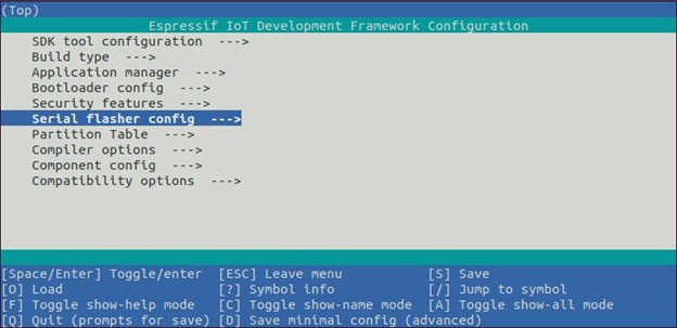
Figure 4: The idf.py menu, provided with the ESP-IDF package. Used for setting up an ESP32 project.
With the fundamental aspects taken care of, the next aspect to look at is the API – what does it look like to actually interface with ESP32 hardware?
The ESP-IDF platform provides a hardware abstraction layer for all of the available peripherals, with the complete reference available here.
In the same Bluetooth example from before this functionality is provided via the following includes in the ble_hidd_demo_main.c file:
#include “esp_system.h”
#include “esp_wifi.h”
#include “esp_event.h”
#include “esp_log.h”
#include “nvs_flash.h”
#include “esp_bt.h”
#include “esp_hidd_prf_api.h”
#include “esp_bt_defs.h”
#include “esp_gap_ble_api.h”
#include “esp_gatts_api.h”
#include “esp_gatt_defs.h”
#include “esp_bt_main.h”
#include “esp_bt_device.h”
#include “driver/gpio.h”
#include “hid_dev.h”
Except for a few example-specific headers that can be found in the same folder as the C file, these includes represent the ESP-IDF API that was required for this example.
The blank line further splits the header files into ‘core’ peripheral driver files on the top and application-specific files on the bottom.
For example, esp_bt.h contains references used by every implementation of the Bluetooth stack on ESP32, and esp_gatts_api.h contains the API for running a Bluetooth GATT server.
So ESP-IDF not only provides core driver functionality but also an API for advanced implementations of peripherals.
Finally, the ESP-IDF examples reference has literally hundreds of examples branching from over a dozen core categories including Ethernet, security, WiFi, and Zigbee.
Combine that with the API reference and it culminates into an enormous amount of documentation, all straight from the developer and updated regularly.
At the time of writing, the Bluetooth HID example was updated within the last month.
Conclusion
Designs based on the ESP32 wireless microcontroller can be as custom or as convenient as your product needs at the various stages of development.
It is a very low-cost solution that has become extremely popular by both makers and product developers. This popularity helps to ensure that there is extensive help and documentation available online.
Not only is the ESP32 a fantastic option for building an early POC prototype, but it is also a great choice for mass manufacturing, whether you use the module on your custom board or you design a custom circuit based on the bare ESP32 chip.

Thank you John for informative article.
Do we have a similar article for PCB design using ESP32? Design considerations , et cetera.
Thank you for the comment, glad you found it helpful. Yes, we are working on an article on how to design a PCB using the ESP32. Thank you for the suggestion.
Thanks, Very useful articles as usual.
Thank you, and great to hear! Glad you found it useful. Thanks for the comment.