
Introduction to Embedded Firmware Development
Learn about embedded firmware development using a simple 8-bit AVR microcontroller.

An embedded system is a stand-alone, intelligent system dedicated to running a set of tasks from the moment it is powered on.
This is in contrast to the way an application is started on a desktop or similar device, since with an embedded system the user does not have to specifically load anything.
An example of an embedded system would be a household washing machine. Once the proper wash cycle is selected and started it will run through a programmed sequence of events.
The intelligence part is determining the water level, performing the wash, rinse and spin cycles, and other related tasks based on user selection.
This demonstrates several aspects of a typical embedded system.
The washing machine has to receive and respond to user selections, sense the water level, and determine the appropriate running time for each operating mode.
The washing machine also needs to control the water shut-off valve and the motor.
Most embedded systems contain a microcontroller at the center of all these operations. This microcontroller is a single, silicon chip that can be programmed to perform all the operations that your application requires.
This is considerably different than a more advanced microprocessor that is designed to run complex applications. See this article for help deciding if you need a microcontroller or a microprocessor for your project.
The programming in our example of a washing machine would have been written by someone in an embedded programming language, and downloaded into the microcontroller during manufacturing.
Let’s look closer at these types of embedded systems. A simple embedded program in the C language, one of the most popular languages for writing embedded applications, is also included.
In embedded firmware programming, the C language, and to a lesser extent C++, is widely used.
The reason for that is that C is arguably still the language that is closest to the hardware, except for assembly language.
While assembly language is closer, it is very specific to the actual underlying hardware, and differs from microcontroller architecture to architecture. C, on the other hand, is much more standardized, while still offering enough control over the underlying hardware.
In order to be able to follow the code example, I’m assuming that the reader already has some knowledge of programming languages other than C.
So, in the code example I won’t spend time on basic concepts like variables, loops, conditional statements, or functions, at least not on the concepts behind them.
What is a Microcontroller?
At the heart of a microcontroller is a Central Processing Unit, or CPU, that is not unlike the ones found in desktop computers, or laptops, except that it is generally less powerful.
This CPU runs the set of instructions, or program, that the original human programmer wrote. Closest to the CPU are some registers. These are temporary storage units that have very fast access times matching that of the CPU itself.
These registers have many functions that the CPU needs in order to run properly.
There is a Program Counter, sometimes called Instruction Pointer, register that contains the address of the next instruction that the CPU will execute.
There is a Stack Pointer register that accesses a special area of memory called a Stack, more on that a little later.
There is a flag register that keeps the result status of some CPU operations, such as the positive or negative results of an arithmetic operation.
Then there are general purpose registers that are used to hold the operations on which the CPU is operating on, as well as holding the result of such operations.
Besides the CPU registers, the CPU is also connected to different peripherals such as IO ports, interrupt controllers, timers, USARTS, SPI, I2C, and, in more advanced microcontrollers, video input or output peripherals and memory management units.
More on some of these peripherals will be presented later.
In addition, the CPU has access to Flash, RAM, and EEPROM memory. All of this is integrated onto a single chip, or Integrated Circuit.
This single chip, with all these integrated peripherals and memory, is the microcontroller.
In contrast, a microprocessor is basically just a very powerful CPU with its registers, and maybe some advanced peripherals, in a chip.
All other peripherals are separate chips that are external to the microprocessor. Of course, these are more powerful, and have more functions compared to those in the single microcontroller chip.
For example, a desktop computer can have 16 MBytes or more of memory, whereas a microcontroller may have as little as 2 KBytes, a factor of 8000X more.
As stated earlier, an embedded application is just a set of tasks that is performed when called upon. Take our example of a common washing machine.

Figure 1 – A washing machine is a common example of an embedded system.
The washing machine accepts the user selection for a given washing cycle, which controls things like the water inlet valve, the time period and temperature for the wash and rinse cycles, the water pump that drains the used water etc..
Additionally, the status, or remaining time, of each operation displayed for the user. All of these tasks are controlled by a microcontroller, built into the washing machine.
Continuing with the example, the controller repeatedly does three steps:
Step 1: Receives inputs such as a start push button, timer countdown, water fill level, etc.
Step 2: Processes the inputs, decides what actions to perform and when to perform them.
Step 3: Acts on the actions decided upon by step 2, and controls some outputs such as water pump, water shut off and fill valve, digital display, etc.
Of course, the actual actions taken will be different for different applications. In this example, step 2 is carried out by the CPU running a pre-programmed set of instructions.
Whereas steps 1 and 3, are performed by the peripherals controlled by the CPU, some of which we’ll cover in the next section below.
Microcontroller Memory and Peripherals
Before getting into proper peripherals, it is worth understanding the memory system of microcontrollers first. All microcontrollers have at least two types of memory: flash and SRAM.
Flash memory is where the user-written program is stored. Like a traditional hard drive in desktop PC’s, the flash memory is non-volatile, and is used to store the program that the CPU will execute.
However, writing to flash memory is comparatively slow, and that is the reason for the SRAM memory. It can be accessed – written to or read from – much faster.
However, it is volatile and thus will lose its content if power to the microcontroller is removed.
The SRAM is usually partitioned into three areas: the general area used to store variables, the heap, and the stack.
The heap is an area of memory that can be accessed on demand in chunks by the running program, and then returned back when no longer needed, whereby it can be requested again by another part of the running program.
The stack is a special section of SRAM that is used to nest function calls, the building blocks of all programs, as well as pass arguments to said functions.
Some microcontrollers also have EEPROM which is also a non-volatile memory type, separate from the flash memory, that is typically used to store user settings or calibration values. Some microcontrollers can actually use a section of flash to do that.
Moving on to the actual peripherals, one thing to note about them is that they can operate in many modes and configurations.
To select the various modes, the first thing to do is to read the datasheet.
All peripherals have configuration registers, several of them. These are different from the CPU registers, and each peripheral has its own set that can be programmed to make the peripheral behave in a certain way.
Since the peripheral registers are not directly accessible by the user, the way to program them is to actually have the CPU run some setup code that, in turn, writes the proper values to the selected peripheral’s registers.
Here are brief descriptions of some common peripherals:
GPIO – These General-Purpose Input Output peripherals can be programmed for logic-level inputs or outputs.
Timers – These can be programmed to provide precise timing, and can output timed pulses, or continuous pulse trains, or can measure the time intervals between two pulse edges.
USARTS – These are used for bi-directional serial communication between two devices, where data is transmitted, or received, bit by bit.
I2C – This is an interface that is used by many modules such as sensors and displays. There can be many such devices on the same communication bus; each can be individually addressed.
SPI – This is another interface with similar functionality to I2C, but is much faster. The choice of I2C or SPI is often dictated by what a particular module uses.
Figure 2 shows the internal blocks of a typical 8-bit microcontroller.
One thing to note about this block diagram is that it shows that only the GPIO ports, here shown as port B, port C and port D, are connected to the externally available pins of the microcontroller.
In the actual microcontroller, these pins are shared among the various peripherals because most microcontrollers have a limited number of externally available pins.
For example, a pin can be programmed to be either a GPIO pin or a USART pin, but not both at the same time.
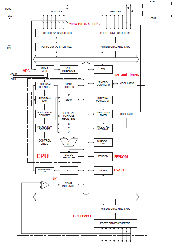
Figure 2 – Major blocks in a typical 8-bit microcontroller
Developing Application Firmware for Microcontrollers
Application software development is usually done on a cross-development platform such as a Windows PC, Linux box or Mac.
The general process is to write the code in an Integrated Development Environment, or IDE, in an embedded language such as C, compile and link the code modules with libraries if used, and download the binary file to the microcontroller for testing and debugging.
This is usually an iterative process.
To expand on the process just described, the IDE simply provides a convenient, all-in-one platform where the process of actually entering the source code, compiling, linking and loading can be done in one place.
Compiling and linking requires a compiler/linker that can generate binary code suitable to the target microcontroller.
Loading can be done in several ways. One, is to have an external device programmer where the target microcontroller is inserted in for loading the compiled binary.
The programmed microcontroller is then inserted into its intended HW module for testing.
Another way is to build a programming interface in the HW board, and program the microcontroller while it is already attached to its hardware.
This method is usually referred to as In-System Programming, or ISP. This is usually referred to as In System Programming.
Yet another way, for some microcontrollers, is to download the binary into the microcontroller through one of its peripherals, usually a USART.
For that to work, the microcontroller must be running a pre-loaded program called a bootloader that receives the new program, and, in turn, updates itself.
Since the bootloader itself is never erased, this means that the microcontroller only has to be externally programmed once with the bootloader code.
Typical microcontroller firmware layout:
// This is a single line comment in C
/*
Multi-line comments are braced with slash-asterisk and asterisk-slash as shown here.
Still a comment line.
*/
// Include header files
// These files contain function prototypes for functions used in this, or other source modules, as well as libraries.
// Some also contain constants and other pre-processor directives, or macros. C has very powerful macro processing capabilities.
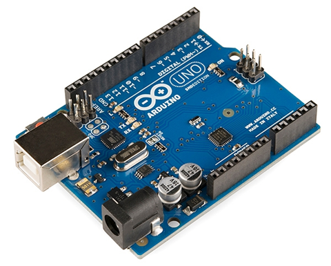
// Here is a simple example based on using an AVR microcontroller such as is used in many Arduino boards such as the Uno.
#include <avr/io.h>
// In C, the program always start with the main() function, regardless of where it is located in the source module. Some
// prefer it to be at the top of the file; others place the main() function as the very last function in the file.
// In embedded applications, main() usually does not have any arguments since there is no command-line arguments to pass to the program at the start.
main() // Can also use void main(void) to emphasize that this main() function takes, and returns, no arguments.
{
// Put peripheral initialization code here, or call functions to do so.
// An embedded application is basically one that runs forever.
while(1)
{
// Application code goes here.
}
}
Below is an actual working example, again based on an AVR microcontroller. It can be used to blink an LED connected to GPIO5 of PORTB of an AVR ATMEGA 328, for example.
Atmel Studio is a free and very suitable IDE plus compiler/linker that can be used for AVR microcontrollers.
// The io.h header file provides names matching those used in the specifications for the peripheral registers.
#include <avr/io.h>
// This one contains function prototypes for the delay functions defined in the avr-libc library.
#include <util/delay.h>
// Function prototypes must be declared if the functions are called before their actual definitions, as is the case here.
// Usually, these are put in a header file that is included in the source module, but they are actually declared here to show how this is done.
void setup(void);
void loop(void);
// Starting point for the program.
void main(void)
{
setup();
while(1)
{
loop();
}
}
// Actual function setup()
void setup(void)
{
// DDRB is the Data Direction Register of Port B, which is 8 bits wide. Each bit corresponds to an actual pin on the microcontroller.
// Setting a bit of this register to 1 means this corresponding pin is an output.
DDRB |= (1 << PB5); // Same DDRB = DDRB | 0b0010000. This sets GPIO5 of PortB as a digital output, and leaves the other GPIO’s untouched.
}
// Actual function loop()
void loop(void)
{
PORTB |= (1 << PB5); // Set PB5 pin of PORTB to 1
_delay_ms(1000); // 1000ms delay
PORTB &= ~(1 << PB5); // Set PB5 pin of PORTB to 0
_delay_ms(1000);
}
Finally, for those who have an Arduino Uno, this program will actually compile, and blink the on-board LED, since the Arduino Uno uses the same GCC compiler for AVR microcontrollers.
Just load a blank sketch. Then, copy the code between the curly braces of function setup() in the setup function of the blank sketch.
Similarly, copy the code between the curly braces of function loop() into the loop function of the sketch. Compile, and run. The LED will start blinking.
Conclusion
This article has been a very simple introduction to programming an embedded microcontroller that primarily focused on a simple 8-bit AVR microcontroller used in various Arduino boards.
For more advanced firmware programming be sure to check out this article on programming the STM32 32-bit Cortex-M series of microcontrollers from ST Microelectronics. Or see this article on programming the ESP32 series of microcontrollers.

Thank you for great article
Great description! Nice balance between simplistic and excessively technical.
Thanks Travis!
As always another great content for the beginner.
Thanks Roomi!