
Datasheet Review: Entry-Level STM32 Cortex-M0 Microcontroller (Blog + Video)

The STM32 line of 32-bit microcontrollers from ST Microelectronics is one of the most popular choices for use in commercial products.
The STM32 line is quite expansive with numerous combinations of performance, peripherals, power, memory, and packages available. In this article and video I’ll be reviewing the datasheet for one of their entry-level models: the STM32F030.
The datasheet for the STM32F030 is ninety-one pages long with way too much information to ever cover in a single blog post or video. Don’t worry, I won’t subject you to that. Instead, we’re going to only review the front page, which lists most of the microcontroller’s key features.
In order to follow along I highly suggest you download the STM32F030 datasheet yourself and refer to the first page. I’ll be reviewing this page on a line-by-line basis. Be sure you read this article and watch the video below to gain the most from this content.
• Core: ARM 32-bit Cortex®-M0 CPU, frequency up to 48 MHz
The first line on the datasheet specifies the CPU core, which is a 32-bit ARM Cortex-M0 architecture processor that can operate with a clock speed up to 48 MHz.
ARM is a separate company that designs processor architectures but doesn’t manufacture their own chips. Instead, they license out their designs to multiple semiconductor manufacturers like ST, TI, Nordic, NXP, Silicon Labs, and many others.
These manufacturers then incorporate ARM processor core designs into their own microcontroller chips.
There are various versions of the ARM Cortex-M line of processor cores. M0 is the lowest performance model, with M7 being the highest performance core in the line.
Cortex microcontrollers are by far the most common microcontroller used in commercial products. In fact, they are used in literally billions of products around the world. The STM32 series is one of the most popular implementations of the Cortex microcontroller architectures, and is my personal favorite line of microcontrollers.
8-bit microcontrollers like the AVR line embedded in Arduinos are mainly used for development boards aimed at makers and DIY’ers. They aren’t as commonly used for commercial products. ARM cores dominate the commercial market and provide better performance for similar cost compared to most 8-bit microcontrollers.
That being said, if you are already familiar with these 8-bit microcontrollers, have developed significant code already, and your product is relatively simple, then they may be a good choice for your product.
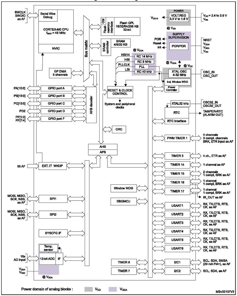
Figure 1 – Complete block diagram STM32F030
• Memories
16 to 256 Kbytes of Flash memory
The STM32F030 microcontroller can support anywhere from 16 KB to 256 KB of flash memory depending on the exact model number. This flash memory is mainly used for storing the firmware program.
4 to 32 Kbytes of SRAM with HW parity
There’s also from 4 KB to 32 KB of SRAM for temporary storage. The SRAM includes hardware parity which is a data check to make sure the data being read has not been corrupted since originally being written.
• CRC calculation unit
CRC stands for Cycle Redundancy Check. This isn’t anything you likely need to worry that much about, it’s just another way of ensuring that digital data isn’t corrupt.
• Reset and power management
Digital & I/O supply: VDD = 2.4 V to 3.6 V
The digital supply voltage, referred to as VDD, can be anywhere from 2.4 V to 3.6 V. This supply is used to power the internal digital circuits (after being sub-regulated down to 1.8V by an internal voltage regulator).
It is also used as the supply voltage for the I/O drivers. This means that all of the GPIO pins will operate at this supply. If you want to interface this microcontroller via a GPIO pin to another chip with a 5V supply voltage, then you would need to use a level shifter.
Analog supply: VDDA = VDD to 3.6 V
A separate analog supply for the Analog-to-Digital Converter (ADC) can be anywhere from a low of VDD (digital I/O supply) up to 3.6 V. The analog supply must be equal to or higher than the digital supply.
For example, if the digital supply is 3V, then the analog supply voltage can be anywhere from 3 V up to 3.6 V.
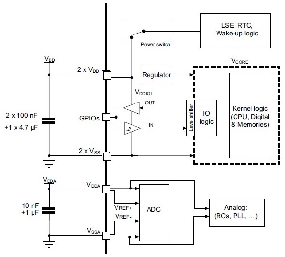
Figure 2 – Power supply scheme for STM32F030 (from datasheet)
Power-on/Power down reset (POR/PDR)
A Power-On Reset (POR), as the names implies, resets the microcontroller when first powered up. This is so the microcontroller always starts in a known state when first turned on.
It does this by monitoring the digital supply. As long as the VDD voltage is below 2V the microcontroller remains in reset mode. Once the supply voltage rises above this threshold the microcontroller becomes active.
The Power-Down Reset (PDR) circuit works in a similar fashion except it is monitoring both the digital and analog supplies for when they fall below the minimum voltage threshold.
These two circuits prevent the microcontroller from activating when powered from a supply voltage too low to guarantee proper functionality.
Low power modes: Sleep, Stop, Standby
As with many microcontrollers, the STM32F030 offers various low power modes of operation called sleep, stop and standby.
When in sleep mode all of the peripherals continue to operate. Only the CPU itself is stopped when in sleep mode. By using interrupts the peripherals can wake up the CPU when needed. Of the three low power modes, sleep mode will consume the most power.
When in stop mode all of the clocks are disabled, but the contents of SRAM and all of the registers is retained. As with the sleep mode, the microcontroller can be awoken from stop mode when an interrupt is detected. Stop mode is the intermediate low power consumption mode.
Standby mode offers the lowest power consumption of these three modes. However, when in standby mode all clocks are stopped, the internal 1.8V regulator is switched off, and the SRAM contents are lost.
• Clock Management
Every digital processor requires a clock signal for timing purposes. There are several clock options with this microcontroller.
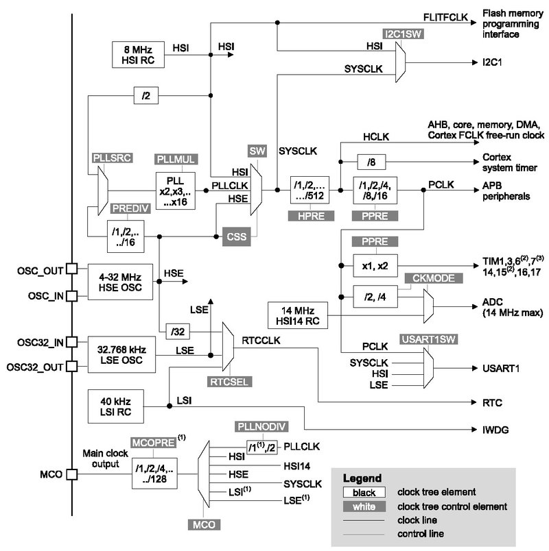
Figure 3 – Clock tree for STM32F030 (from datasheet)
4 to 32 MHz crystal oscillator
You can use an external crystal oscillator with a frequency between 4 MHz and 32 MHz. This will provide the most accurate clock source.
32 kHz oscillator for RTC with calibration
For the Real-Time-Clock (RTC) an external 32.768 kHz crystal should be used. This frequency is commonly used for real-time clock applications because it is a power of 2, such that 2^15 = 32768. This makes it easy to internally divide the clock signal down to a very precise 1 Hz signal (one cycle per second).
The RTC includes an internal calibration circuit to keep the oscillator clock signal exactly precise for timing purposes.
Internal 8 MHz RC with x6 PLL option
Other possible clocks include an internal 8 MHz RC oscillator. An RC oscillator means an oscillator based on the timing characteristics of a resistor (R) and a capacitor (C).
The advantage of an RC clock over a crystal clock is that an RC oscillator can be easily embedded inside the microcontroller chip, whereas a crystal oscillator requires an extra external component.
The downside of an RC oscillator is their frequency accuracy isn’t all that great. If you need precise timing, you’ll want to use a crystal oscillator.
The 8MHz RC clock has a 6-X PLL option. PLL is the abbreviation for Phase-Locked Loop, which is a complex subject beyond the scope of this article. But essentially, this is just a 6-X frequency multiplier. So it takes the 8MHz RC oscillator frequency, multiplies it by 6x, and outputs a 48 MHz clock signal.
Internal 40 kHz RC oscillator
Finally, there’s also an independent 40 kHz RC oscillator built-in which is used for the watchdog function which I explain further below.
• Up to 55 fast I/Os
This STM32 supports up to 55 different GPIO pins. The exact number depends on the model number and package. The higher pin count packages will almost always support a higher number of I/O pins
All mappable on external interrupt vectors
This means that any of the I/O pins can be used as an interrupt. An interrupt is just a signal that can come from an external peripheral which alerts the processor that it needs to do something.
You can have what are called interrupt service routines so that whenever one of these interrupt pins is triggered by an external device, the microcontroller will then execute the appropriate routine associated with that interrupt pin.
Up to 55 I/Os with 5V tolerant capability
All of the GPIO pins on the STM32F030 are specified as being 5V-tolerant even though the maximum I/O supply voltage is only 3.6V. This means a GPIO programmed as an input pin can safely be fed a 5V digital signal.
Be warned though this doesn’t mean you can output a 3.6V signal and feed it to an input pin on a device with 5V I/O. The I/O pins being 5V tolerant only helps on pins programmed as inputs.
• 5-channel DMA controller
A Direct Memory Access (DMA) controller allows external memory or peripherals to communicate directly with the internal memory without the central processing unit (CPU) having to be involved in that communication.
Using a DMA frees up the CPU to keep on processing without having to deal with shuffling data around. A DMA allows you to get data in and out of the microcontroller, without having to interrupt the core processor.
• One 12-bit, 1.0 μs ADC (up to 16 channels)
An Analog-to-Digital Converter (ADC) converts an analog voltage to a digital reading that the microcontroller can then process. This STM32 microcontroller has a 12-bit ADC with 16 channels. This means the analog voltage will be converted to a 12-bit digital code.
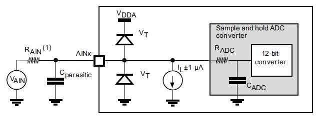
Figure 4 – Typical ADC connection diagram
Conversion range: 0 to 3.6 V
The maximum number represented with a 12-bit code is 2^12 = 4,096. The analog input range can be between 0 and 3.6V. To calculate the smallest increment in analog voltage that can be measured with this 12-bit ADC you take voltage range and divide by 2^12 = 4,096.
This means the smallest voltage change that can be measured by this ADC is 3.6 V / 4,096 = 0.88 mV when using a 3.6 V analog supply. Smaller increments are possible with lower voltage analog supplies.
Separate analog supply: 2.4 V to 3.6 V
A separate supply is almost used for powering an ADC because of the low noise requirement. You don’t want the digital noise to couple into the ADC because it can cause significant error in measurements.
A very clean, stable supply typically filtered through an LC (inductor-capacitor) low-pass filter should be used for the analog supply.
• Calendar RTC with alarm and periodic wakeup
A calendar RTC (Real-Time Clock) feature allows the microcontroller to measure not only time, but also to keep track of the current date and time. The STM32F030’s calendar RTC also includes an alarm and periodic wakeup functionality.
• 11 timers
Most microcontrollers, if not all, include various timers which are used for lots of different applications.
One 16-bit advanced-control timer for six-channel PWM output
One common use of a microcontroller is to generate PWM signals. PWM stands for Pulse-Width Modulation. A PWM signal is generated with a specific on-time and off-time ratio. This ratio can be used for all kinds of purposes such as controlling a motor.
The STM32F0 has one 16-bit timer specifically for use with a six-channel PWM output.
Up to seven 16-bit timers
It also includes up to seven (number depends on exact model) other 16-bit timers for general purpose uses.
Independent and system watchdog timers
As with most microcontrollers the STM32F0 also includes what is known as a watchdog timer.
A watchdog timer will reset a microcontroller if it gets locked up. A watchdog routine must be regularly updated by the processor. If this doesn’t occur, then the watchdog routines knows that the processor has locked up and a reset is automatically initiated.
SysTick timer
Then last up is SysTick timer. This is a system timer that generates regular interrupts. This is mainly used if you’re going to run a Real-Time Operating System (RTOS) on the microcontroller.
Most applications do not need to run an operating system for microcontrollers, but if you need an OS for your application then you will use this timer.
• Communication interfaces
A microcontroller that can’t communicate with the world outside its own chip isn’t of much use. Various interfaces are critical to allow the microcontroller to communicate with other chips, sensors, displays, cameras, etc.
Up to two I2C interfaces
I2C is a very common, two-pin serial interface. There’s only a clock pin (called SCL) and a data pin (called SDA). This makes it ideal for connecting multiple devices on the same PCB with very little routing space required.
I2C is also an addressable bus protocol so you can connect many different peripherals using only those same two lines. Each device will have its own unique address. You can put multiple devices on these same two wires, and then you can address each one separately. Each device will know when it is the one being talked to.
It’s not a super high-speed serial communication protocol, but it’s really handy to use for any on-board low-speed communication. It’s especially common to use this protocol for communicating with various types of sensors.
The STM32F030 supports speeds up to 1 Mbps on both I2C interfaces. It also supports SMBus/PMBus which are two-wire protocols derived from I2C but that are specifically used for communicating with power sources.
Up to six USARTs
USART stands for Universal Synchronous Asynchronous Receiver Transmitter. Whew, that’s a mouthful.
Perhaps you’ve instead heard of a UART which offers only asynchronous (notice the ‘S’ is gone for synchronous) communication. Synchronous communication means there’s a clock signal shared between the two devices communicating for timing purposes.
There are STM32F030 variants that provide up to six USART interfaces which can support both synchronous and asynchronous communication.
Up to two SPIs (18 Mbit/s)
SPI is a much faster interface which supports up to 18 Mbps, whereas I2C only supports 1 Mbps, making SPI roughly 18 times faster. Both I2C and SPI are synchronous protocols with a shared clock signal.
SPI can be used for more data-intensive peripherals, such as interfacing with a display, whereas I2C is a better choice for low-data peripherals such as sensors. A downside of SPI compared to I2C is that it requires at least three wires versus only two for I2C.
With I2C, data flows in both directions along a single data line. Whereas SPI has two data lines, one for each direction of data flow.
Because SPI isn’t an addressable bus protocol, a 4th signal line called Slave Select (SS) is commonly needed to ensure that only one device on the SPI lines is active at one time.
If you have peripherals A and B connected to the same SPI port, and you wish to communicate with device B, then you must disable device A and enable device B. It’s not nearly as elegant a solution as provided by I2C.
• Serial wire debug (SWD)
Serial Wire Debug (SWD) is the interface you will use to connect to the microcontroller for programming and debug purposes. Like I2C, SWD is a two-wire synchronous communication protocol.
Unlike programming an Arduino, most microcontrollers require a special programming device to program your firmware into the flash memory.
The most common choice for the STM32 series is the ST-LINK which supports SWD, JTAG, and SWIM programming interfaces.
The ST-LINK will connect to your computer via USB, but will then interface with the microcontroller using SWD.
• Packages
The STM32F030 is available in a QFP package or a TSSOP package. The TSSOP package is only available in a 20-pin version so it will have limited features and GPIO pins available.
For the QFP package there are three pin count versions: 32 pins, 48 pins, and 64 pins. The QFP-32 and QFP-48 measure 7 mm x 7 mm. The QFP-64 measures 10 mm x 10 mm.
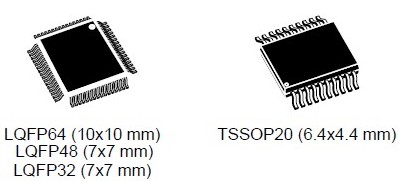
Figure 5 – Available packages for STM32F030
Both of these packages are known as leaded packages. This means the pins actually come out the side of the package. Once they’re soldered onto the board, you can still access the pins.
This is in contrast to leadless packages, such as QFN or BGA packages, for instance. For these packages the pins are actually underneath the plastic, so once they’re soldered down, you can’t access the pins.
In most cases I recommend using a leaded package, unless you need to squeeze every fraction of a millimeter out of the design, or if a certain chip only comes in a leadless package.
First of all they make it easier to debug any hardware issues because you can easily access all the pins without adding test points.
They also are cheaper to solder onto the printed circuit board which can lower your prototype and manufacturing cost.
Conclusion
The STM32F030 is good entry level Cortex-M0 microcontroller with a wide selection of peripherals. But there are hundreds of models in the STM32 lineup so you need to select the model with the performance and feature set that fits best with your product’s requirements.
Based on what you’ve learned from this STM32F030 datasheet review, you should now have the knowledge to select the best microcontroller for your project.
If you have any questions please post them below as a comment and I will be happy to answer them. Also, if you’d like me to do a datasheet review on a specific component please comment below.

Yes me too join with you….
That’s quite handy, nice article kudos to you. Anyway I will really quite appreciate if you cover low power microcontroller Texas Instruments. Anyway once again great article and hope you are having great day.
Deepest Regards
Thank you for the comment! I’ll definitely add reviewing a low-power TI MCU to my blog list.
i just wanted to say thank for that piece of knowledge, i love the blog..though i never say thank to so many bloggers, for you i take heart.you are really a thoughtful person for sharing this information…cant wait for more.love all the way from Kenya.
Wow, thank you Mwenda all the way from Kenya! I do always try to be a thoughtful person, and I really enjoy helping others work toward a dream!
Best wishes,
John
Thanks for this article. This is very helpful. If your application requires a camera with say a Camera Serial Interface (CSI), how does that interface with a microcontroller?
Hi Mehul,
Thanks for the comment. To my knowledge no microcontroller currently supports MIPI-CSI interfaces. The STM32F4 series only supports the MIPI-DSI (Display Serial Interface). MIPI-CSI is for now the realm of more advanced microprocessors. One option is to use a specialized video processor chip that interfaces with the camera via CSI but then outputs the data as USB, or perhaps in parallel DVP (Digital Video Port) format.
John