
Linear and Switching Voltage Regulators: An Introduction
Learn the basics of both simple linear regulators and more complex switching regulators.

Voltage regulators are an essential part of most electronic hardware products. The function of a voltage regulator is to provide a stable voltage on the output of the regulator while the input voltage can be variable.
Regulators (as well as battery chargers) can be broadly classified as linear or switching. Since linear regulators are much easier understand we’ll start with them, and then move on to more complex switching regulators.
Linear Regulators
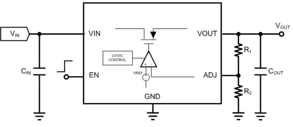
Linear regulators can be thought of as variable resistance devices, where the internal resistance is varied in order to maintain a constant output voltage. In reality, the variable resistance is provided by means of a transistor controlled by an amplifier feedback loop.
Linear regulators normally consist of a minimal of three pins – an input input, an output pin, and a ground pin.
External capacitors are placed on the input and output terminals to provide filtering and to improve the transient response to sudden load changes. The output capacitor is also required for stability of the voltage regulator’s feedback loop.
The amount of current flowing through the regulator, and the amount of power dissipated in the device, will influence the device package selection and heat sink requirements.
Linear regulators are much less efficient than switching regulators and therefore waste more power which dissipates as heat.
If the device will dissipate more than 100 mW, it is recommended that a more thorough thermal analysis be performed that considers maximum operating temperature and the thermal resistance of the IC package (known as Theta-JA).
If a regulator specifies a theta-JA of 50C/W, then that means the IC temperature itself (called the junction temperature) will rise 50C for each watt of power dissipated.
Most IC’s are rated up to a junction temperature of 125C. So for example, if a regulator with a theta-JA of 50C/W is dissipating 1W, then the maximum ambient temperature it can be used in will be 125C – 50C = 75C.
Linear regulators require an input voltage that is higher than the output. The minimum voltage level difference between the input and the output is called the dropout voltage. For a normal linear voltage regulator the dropout is about 2 volts.
Low dropout (LDO) regulators can regulate down to less than 100mV. However, their ability to reject noise and ripple on the input supply will be significantly reduced below about 500mV.
For most applications a linear regulator, or more specifically a LDO regulator, makes more sense if the input voltage is no more than a couple volts above the output voltage.
Otherwise, the regulator will waste too much power and a more efficient switching regulator is a better option.
Linear regulators have three main advantages. They are simple, cheap, and provide exceptionally “clean” voltage outputs.
Switching Regulators
Switching regulators convert one voltage to another by temporarily storing energy and then releasing that stored energy to the output at a different voltage.
The terms DC to DC converter, switched mode power supply (SMPS), switching regulator, and switching converter all refer to the same thing. These operate by controlling a solid state device, like a transistor or diode, that acts like a switch.
The switch interrupts the flow of current to an energy storage component, such as a capacitor or an inductor, in order to transform one voltage to another.
There are many types of switching regulator topologies including the three most common ones:
Buck (Step-Down) Switching Regulators
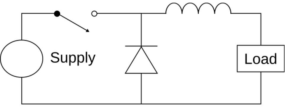
A buck converter can step-down a higher voltage on the input to a lower voltage on the output. This is similar to a linear regulator, except a buck regulator will waste much less power.
If the input voltage is much higher than the desired output voltage a buck regulator is usually preferable to a linear regulator.
Boost (Step-Up) Switching Regulators
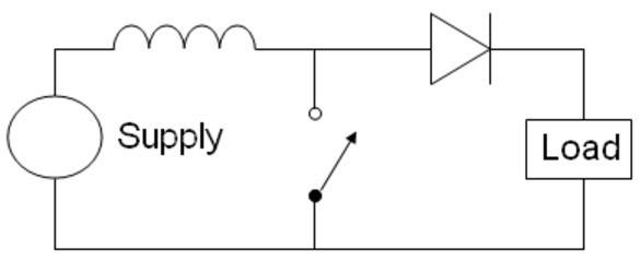
A boost converter is capable of developing a higher voltage on the output than the input. For example, a boost converter can be used to generate 5VDC or 12VDC from a single 3.7VDC lithium-ion battery.
Buck/Boost (Step-Down/Up) Switching Regulators
A buck/boost converter, as you might have guessed, is capable of supplying a fixed output voltage from an input voltage that can vary above and below the output voltage.
This type of a voltage regulator is very useful in battery operated equipment, where the input voltage decreases with time.
The most basic topology is simply the buck converter circuit above followed by the boost converter circuit. The two inductors end up in series so can be combined into a single inductor.
In this tutorial I design a PCB using a simple linear regulator, and in this more in-depth course I design a custom board using a more complex switching regulator.
Summary of Common Specifications for Voltage Regulators
Whether the voltage regulator is a linear regulator or a switch mode regulator, designers need a basic understanding of the parameters that characterize the performance of the regulator.
Output Voltage: The output voltage can be fixed or adjustable. If fixed, the voltage is set internally to the device and you purchase the specific part number for the output voltage that you want.
If the regulator is the adjustable type, the voltage is usually set by a voltage divider made up of two resistors. This offers some flexibility, but at the cost of extra components.
Input Voltage: The minimum and maximum input voltage specified needs to be strictly adhered to. They simply won’t work below the minimum voltage, and will be damaged if operated above the maximum voltage.
Current Output: The maximum current the voltage regulator can provide is limited and is usually determined by the current carrying capability of the internal power transistor. All IC regulator solutions include a built-in current limit circuit to prevent damage.
Output Ripple or Power Supply Rejection Ratio (PSRR): Output ripple refers to the small variations in the output voltage. The amount of ripple in the output voltage is very important to consider since many types of circuits will be sensitive to any noise on their input supply.
Linear regulators reject input ripple without adding additional ripple. Their ability to reject ripple is specified by Power Supply Rejection Ratio (PSRR). The higher the PSRR then the better the linear regulator is at rejecting any ripple on the input voltage.
Switching regulators on the other hand create output ripple by their switching nature. The amount of ripple from a switching converter can be reduced by filtering and careful component selection.
A common design technique is to use a switching regulator to step down the supply voltage with minimal power dissipation, followed by a linear regulator to remove any ripple.
Many low-noise, high-PSRR linear regulators feature an extra pin commonly called the NR pin, or noise-reduction pin. Placing a capacitor of around 10nF on this pin to ground helps to filter out noise and ripple on the internal voltage reference and thus the output voltage.
Noise: Many electronic components, such as resistors and transistors, also produce a fundamental physical noise that is commonly confused with ripple. Noise will show as random fluctuations on the output voltage versus ripple will show up as a small periodic waveform.
Although not related to ripple the same techniques that reduce output ripple also typically reduce noise – mainly the use of the noise-reduction capacitor.
Load Regulation: Load regulation refers to the ability of the regulator to keep the output voltage steady when the load current changes. This specification is often provided in the device datasheet as a plot of output voltage versus load current.
Line Regulation: Variations in the voltage input to the regulator can cause variations in the output voltage, and line regulation is a measure of this variation.
Line Transient: This is a measure of how the output voltage responds to a sudden step change in the input voltage. As with a load transient there will be a small overshoot or undershoot in the output voltage as the regulator’s feedback loop responds to the sudden change. Regulators with a high-PSRR specification (i.e. low output ripple) typically have the best line transient performance.
Voltage Drop-out: The drop-out voltage for classic linear regulators such as the LM317 or LM78xx series is about 2 volts. This means that the input voltage must be at least 2 volts higher than the output voltage for the regulator to work.
Low drop-out (LDO) regulators can work with an input to output voltage difference that is much smaller. For example the TPS732 family of low drop-out regulators has a voltage input range of 1.7 to 5.5 volts and a drop-out voltage of 40mV at 250 mA.
Efficiency: Efficiency is a measure of how much power is wasted by the regulator. As previously mentioned a linear regulator wastes a lot more power than a switching regulator. This means a linear regulator has a much lower efficiency. Efficiency can be calculated by dividing the output power by the input power.
So if the output power is the same as the input power then efficiency is 100% and the regulator wastes no power. This is the ideal, but unattainable scenario. Most switching regulators have an efficiency between 80-90%.
The efficiency of a linear regulator varies with the ratio of the input voltage to the output voltage. This is because for a linear regulator the input current is always essentially identical to the output current.
Since power is equal to voltage times current the currents in the efficiency equation cancel out only leaving the voltages. This means the bigger the difference between the input voltage and the output voltage the worse the efficiency for a linear regulator.
So for example, for a linear regulator with a 5VDC input voltage and a 3.3VDC output voltage the efficiency is:
Efficiency = 3.3VDC / 5VDC = 66%
But if the input voltage is increased to 12VDC the efficiency drops to
Efficiency = 3.3VDC / 12VDC = 27.5%
which means 72.5% of the power is being wasted by the linear regulator!
The main advantage of a low-dropout regulator is they allow an output voltage very close to the input voltage meaning the efficiency of the regulator is much higher.
For example, if generating a 3.3VDC output voltage from a 3.7VDC lithium-ion battery an LDO with a dropout less than 400mV is required. At these voltages the efficiency is 3.3VDC / 3.7VDC = 89% which is comparable to a high efficiency buck regulator.
Unlike with a linear regulator, an ideal switching regulator will have an efficiency of 100% which means the input power equals the output power. This means the input current will never be the same as the output current.
In fact, the input current will always be less than the output current for a buck regulator, and it will always be higher than the output current for a boost regulator.
Output capacitor: The size of the output capacitor is critical for both linear and switching regulators so be sure to follow the recommendations in the datasheet. In most cases a ceramic capacitor (with an X7R or X5R thermal rating) is the best choice.
Ceramic capacitors have very low parasitic resistance (called Equivalent Series Resistance or ESR) which usually improves the transient response of the regulator. Be careful though because some regulators require the use of tantalum capacitors with a higher ESR in order to stabilize the feedback control loop.
Electromagnetic interference (EMI)
One concern when designing with switch mode power supplies is the potential for electromagnetic interference (EMI).
The switching action of the active device, which can be at frequencies that range from 100’s of kilohertz to several megahertz, can generate a broad spectrum of emissions. These emissions can be conducted and radiated to nearby equipment causing harmful interference or even self interference.
Be aware that the PCB layout for a switching regulator is very critical, much more so than with a linear regulator. So be sure to follow the layout guidelines in the datasheet very closely.
If no layout guidelines are provided in the datasheet for the switching regulator you’ve selected, then I highly recommend choosing a different regulator.
Conclusion
When power efficiency isn’t a concern, or when the input voltage is only slightly higher than the output voltage, the best choice is usually a linear regulator. Linear regulators are typically cheaper, less complex, and require fewer components.
If a really clean, ripple-free output voltage is required then a linear regulator is also the best choice.
On the other hand, if power efficiency is a key concern, or the input voltage is much higher than the desired output voltage, then a buck switching converter is the better choice.
If an output voltage higher than the input voltage is required then the choice is easy – only a boost regulator can perform that trick.
As with all aspects of engineering there are always trade-offs between various solutions. Many times the best solution is a switching regulator followed by a linear regulator. This way you get the best of both worlds: efficiency and a super clean output voltage.

Hi, I want to use a circuit powered with 5V with a battery of 20V (of drill). What is the best solution to have with less power consumption?
If you wish to step down the 20V to 5V then you will need to use a buck switching regulator. This would likely be too much power consumption for a linear regulator, unless the load current is very low.
Thanks a lot. I really appreciate. Consumption is 30mA (arduino nano and some components). Do you know if it can survive at least 5 days (6hours per day), based on the fact we use a battery of 20V/3A?
For only 30mA you can probably get by with a much less complex linear regulator. How long the battery lasts depends on the battery capacity in mAh, not the voltage or maximum current rating.
Thanks a lot.
Your article regarding the linear type voltage regulator is very knowledgable & beneficial in terms of understanding the concept of Voltage Controller
Thanks for the post you shared. The voltage regulator you are talking about works great, but does the automatic voltage regulator work so well? I am really very disturbed
Thanks for the comment. I’m not sure I understand your question though. What do you mean by the automatic voltage regulator? That articles discusses linear and switching regulators.
Best regards, John
Very useful and clear explanation, John. Great!!!
And I absolutely agree with your last advice before Conclusion: if the manufacturer doesn’t publish any layout recommendations for its switching regulator device, better choose another one… or prepare your oscilloscope and be willing to solve many problems.
Thanks for the comment Inigo!
Hello, thank you for this article. I have a question please regarding the linear regulator. I have a schematics that uses the LM1086. It seems that the Vout is 3.3 V according to the measurement. Vout = 1.25 (1+ 200Ohms/120Ohms) = 3.3 V. The caps used are 10uF. However, I noticed that if I plug the power supply I see a huge overshoot on the Vout = 20V peak to peak sometimes. Does that mean that the pcb is not protected? Some pcbs show failure and I m trying to understand what’s wrong. How can I overcome this please if that’s the problem? Better capacitor values? Thank you in advance.
Hey thanks for the comment and question. To really answer your question in detail I’d need a little more information. Any chance the input is spiking higher than the maximum rated voltage? Are the input and output capacitors placed right near the LM1086? How long does the output voltage spike last? You may need to add a zener diode to either the input or output voltage to clamp the voltage from going too high. A 20V spike on a 3.3V supply can definitely cause some damage. You may also consider adding a LC low-pass filter on either the input or output.
Best regards,
John
Nice article john.
Thanks for the comment Vasanth!
Best regards,
John
Nicely done. Vert informative, clear, and concise.
Thanks Lawrence, I appreciate the positive comment!
Best regards,
John
Another great article.
Effective immediately you are hereby appointed to Youtube contributor. I look forward to your
videos !!!
Hey Mike, thanks for the nice comment! Making Youtube videos is definitely on my list for the near future.
Best wishes,
John