
How to Build a GSM Cellular Panic Alarm Using an Arduino
In this article, I’m going to show you how to build a proactive panic alarm system that can be triggered from a wireless remote (in case you’re home) or from your smartphone (if you’re outdoors).

While security cameras do a decent job of passively monitoring background activities, they do little to deter intruders or prevent emergencies like fire, flood or theft.
Of course, you can always call 9-1-1 in case an unfortunate event occurs, but shouldn’t security be more proactive, rather than being simply reactive?
I’ll teach you how to make an improved system that will send instant SMS alerts to the preconfigured mobile numbers in case of an emergency, and function normally even if the electrical or network cabling of your home is cut-off (since it runs on GSM network).
Here’s What You’ll Need for the Project:
► 1x Arduino Uno
► 1x Arduino Nano
► 2x nRF24L01 2.4 GHz Wireless Transceivers
► 1x SIM900A GSM/GPRS module
► 1x SIM card
► 1x Piezo Buzzer
► 1x Push-button
► 1x 10k Ohm resistor
► 2x 10μF electrolytic capacitor (for removing noise)
► 2x Breadboard (for prototyping)
► 2x 3.3V voltage regulator (optional)
► Jumper wires
For the project, I would be using two different Arduino MCU boards. The central security controller runs on the Arduino UNO, while the panic button remote operates on the Arduino Nano.
Functionally, there’s not much difference between the boards (you can really use any Arduino board), but I chose the Nano, as it’s smaller in size and ideal for prototyping the panic button remote circuit on a breadboard.
For establishing the radio link between the controller and the panic button remote, I have used nRF24L01 transceiver modules, which are pretty cheap and reliable.
They operate using a 2.4 GHz RF carrier just as with Bluetooth and WiFi. Although I have used the basic transceiver model for prototyping, you can always pick higher variants with a power amplifier and an SMA antenna that offer an extended wireless range (~1km).
Lastly, I have used the SIM900A GSM/GPRS module for sending/receiving text messages. In case you’re unable to get your hands on a SIM900A module, you can use any equivalent modules (SIM800A/SIM800L) or even opt for the slightly expensive Arduino GSM shield.
High-Level Overview
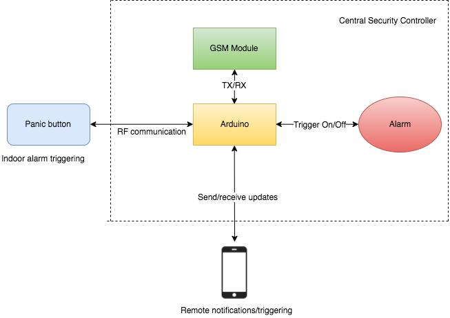
Before going into the nitty-gritty of the hardware design and code, let’s first understand how the setup works on a higher level. As you can see from the above block diagram, the central security controller has a single Arduino MCU that’s connected to the GSM module (via the UART Tx-Rx lines), and a piezo buzzer.
The Arduino maintains an active radio link with the panic button (via nRF24L01) and constantly listens for the coded signals. As soon as the code for the panic signal is received from the remote, the controller triggers the buzzer and notifies the owner via text message.
To turn the alarm off, the owner can either send a pre-configured text message from the registered number or simply press the disarm button.
Central Security Controller
Hardware Design
Here’s what the hardware prototype of our central security controller looks like:
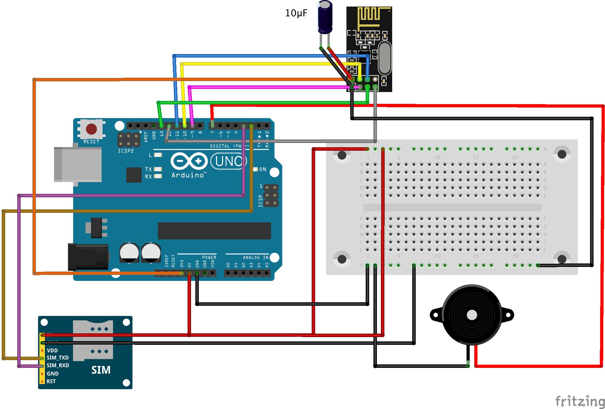
As you can make out from the above sketch, I have connected the Tx and Rx of the SIM900A module with digital pins 2 and 3 of the Arduino respectively. The positive leg of the piezo buzzer is connected to digital I/O pin 7 of the Uno, while the negative terminal is connected to Arduino GND.
Lastly, I have connected the nRF24L01 transceiver module with the Arduino Uno in the following configuration:
|
nRF24L01 |
Arduino Uno |
|
GND |
GND |
|
VCC |
3,3V |
|
CE |
9 |
|
CSN |
10 |
|
SCK |
13 |
|
MOSI |
11 |
|
MISO |
12 |
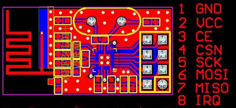
Since most nRF24L01 modules don’t have the pins labelled on the circuit, here’s the pinout diagram for your reference:
To improve the signal strength and reduce the packet loss, I recommend connecting a 10μF electrolytic capacitor between the VCC and GND of the transceiver module. This capacitor helps to supply any fast current transients required by the RF module.
WARNING: Unless you’re using an external base module with a voltage regulator and bypass capacitors, all nRF24L01 transceivers are 3.3V modules. While the I/O pins are 5V tolerant, connecting the VCC of nRF24L01 with Arduino’s 5V regulated supply could damage your transceiver.
Programming the Central Security Controller
Once you have connected all the hardware components for the security controller, the next step is to program the circuit. But before we move on to the actual code, you’ll need to first download the following RF library and install it on your Arduino IDE:
https://github.com/maniacbug/RF24
NOTE: Please note that there are multiple versions of RF24 available on the Github repository. So, in case you get an error while compiling the below code, delete your existing RF24 library and install the one linked above.
Here’s the code that you’ll need to copy-paste in your Arduino IDE:
#include <SoftwareSerial.h>
#include <SPI.h>
#include <nRF24L01.h>
#include <RF24.h>
#include <RF24_config.h>
/*
This sketch sends a string to a corresponding Arduino
with nRF24 attached. It appends a specific value
(2 in this case) to the end to signify the end of the
message.
*/
int msg[1];
RF24 radio(9,10);
const uint64_t pipe = 0xE8E8F0F0E1LL;
int lastmsg = 1;
String theMessage = “”;
String mobileNumber = “+xxxxxxxxxx”; // Replace it with your mobile number
String passphrase = “YOURPASSPHRASE”;
String armCode = passphrase;
String disarmCode = passphrase;
SoftwareSerial mySerial(2, 3); // Tx, Rx
String readString=“”;
String number = “”;
int checkFlag = 0;
int messageFlag = 0;
String message = “”;
const int buzzer = 7;
int messageLength = passphrase.length()+2; // Increase the length by two for operation code
void setup()
{
mySerial.begin(9600); // Setting the baud rate of GSM Module
Serial.begin(9600); // Setting the baud rate of Serial Monitor (Arduino)
delay(100);
radio.begin(); //Start listening for signals on the nRF radio
radio.openReadingPipe(1,pipe);
radio.startListening();
delay(200);
Serial.println(“Device Setup Complete.”);
pinMode(buzzer,OUTPUT);
receiveMessage();
armCode += “AA”; // Code AA for arming the system
disarmCode += “BB”; // Code BB for arming the system
}
void loop() {
checkMessages(); // Check for messages from smartphone
checkRadio(); // Check for any panic signals
}
void sendMessage() {
mySerial.println(“AT+CMGF=1”); //Sets the GSM Module in Text Mode
delay(1000); // Delay of 1000 milli seconds or 1 second
mySerial.println(“AT+CMGS=\”+xxxxxxxxxx\”\r”); // Replace xxxx… with mobile number
delay(1000);
mySerial.println(“Security Alert from Home!”);// The SMS text you want to send
delay(100);
mySerial.println((char)26);// ASCII code of CTRL+Z
delay(1000);
}
void receiveMessage() {
mySerial.println(“AT+CNMI=2,2,0,0,0”); // AT Command to receive a live SMS
delay(1000);
}
void validate(String number, String message){
if(number.equals(mobileNumber)){
if(message.equals(“ARM”)>0){
Serial.println(“ALERT!”);
arm();
}
else if(message.equals(“DISARM”)>0){
Serial.println(“DISARM!”);
disarm();
}
}
}
void arm () {
digitalWrite(buzzer,HIGH);//make a sound
}
void disarm () {
digitalWrite(buzzer,LOW);//silent
}
void checkMessages() {
if (mySerial.available()>0){
readString = mySerial.readString();
if(readString.length()>30) {
Serial.print(“The module received a message from:”);
int startNumber = readString.indexOf(‘”‘);
int EndNumber = readString.indexOf(‘”‘, startNumber+1);
number = readString.substring(startNumber+1, EndNumber);
Serial.println(number);
int startMessage = readString.lastIndexOf(‘”‘);
message = readString.substring(startMessage+1,readString.length()-1);
message = message.substring(message.indexOf(‘\n’)+1,message.length()-1);
Serial.print(“The message was:”);
Serial.println(message);
}
else if(readString.lastIndexOf(‘+’)==2){
Serial.println(“The module is now actively listening to incoming messages.”);
}
if(number!=“” && message!=“”){
validate(number, message);
}
}
}
void checkRadio() {
if (radio.available()){
bool done = false;
done = radio.read(msg, 1);
char theChar = msg[0];
if (msg[0] != 2){ // We detect that the message has ended when we detect a 2.
theMessage.concat(theChar);
}
else {
if (theMessage.length() == messageLength) {
if(theMessage.equals(armCode)){
arm(); // Trigger the local alarm
sendMessage(); //Send the notification to the programmed number
}
else if(theMessage.equals(disarmCode)){
disarm(); // Trigger the local alarm
sendMessage(); //Send the notification to the programmed number
}
}
theMessage= “”;
}
}
}
Now, before you go off and run the code on your Arduino, there are a couple of changes that you’ll need to make:
Mobile number: The controller has been programmed to recognize and process text-messages only from a predefined mobile number. So, you’ll need to replace +xxxxxxxxxx with your number.
Secret passphrase: To make the RF communication secure, we append the arm and disarm commands with a secret passphrase. The default passphrase is “YOURPASSPHRASE”, but you can put any string here.
Testing
Once you have made the above changes, you can compile the code and run it on your Arduino board. When you run your code for the first time, you should be able to see an output window that looks something like this:
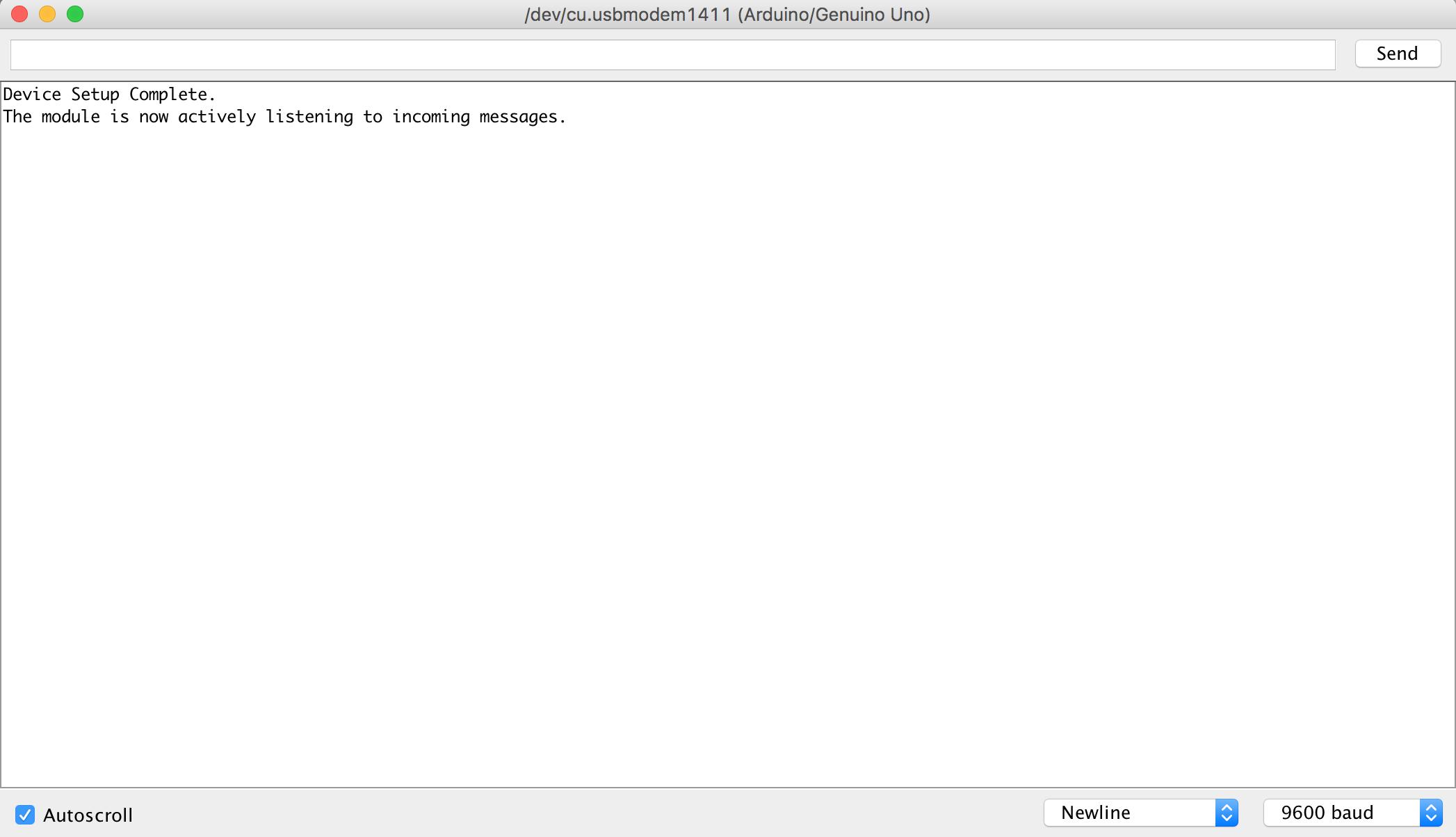
Try sending a text message from your number to the controller number. You would be able to see the output on the Serial monitor:
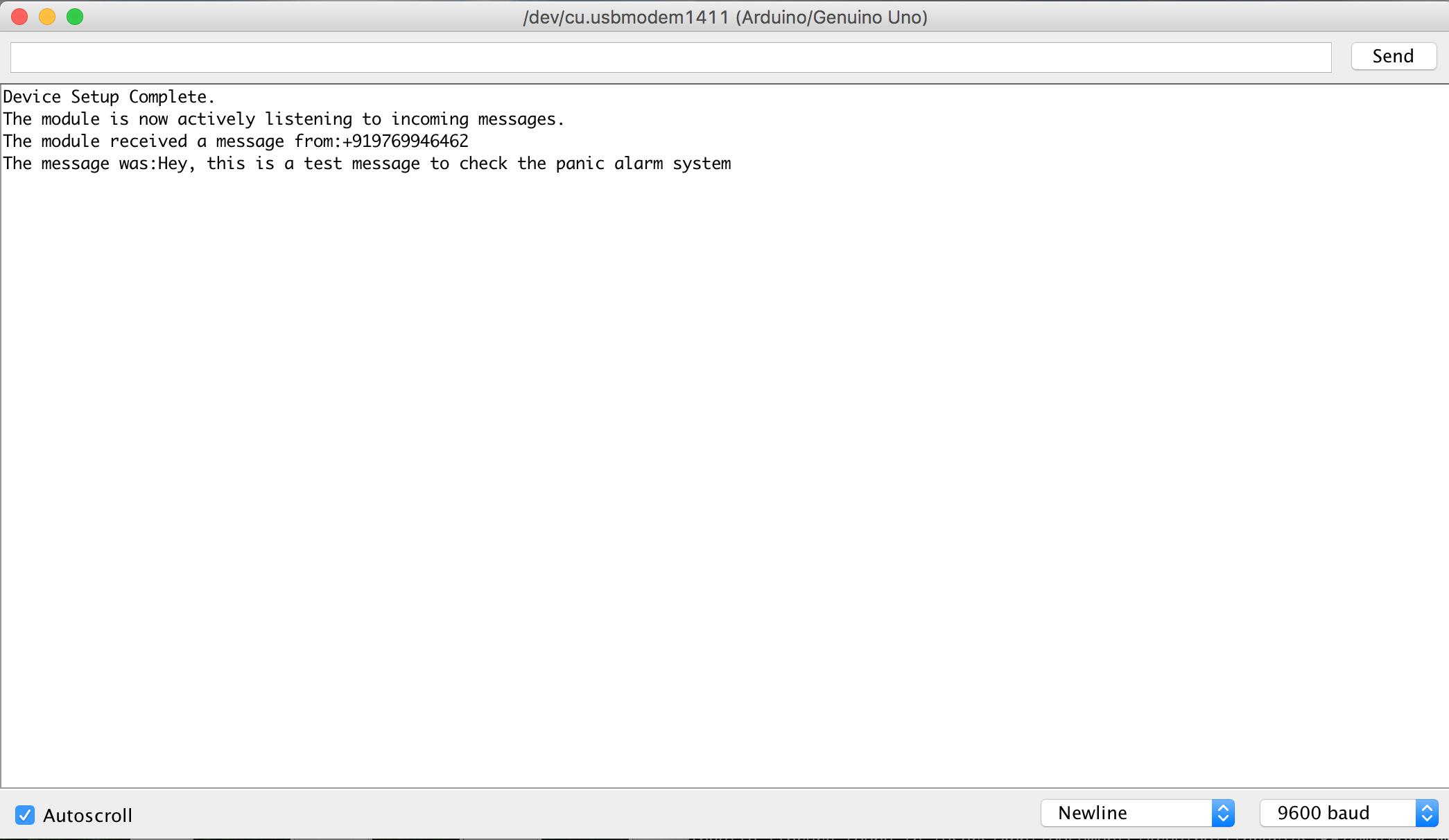
Lastly, try sending the arm button code to the controller through your smartphone. The buzzer should go off and you’ll be able to see an alert on the Serial monitor:

Panic Button Remote
Now that we have the central controller up and running, the final step is to make a simple panic button remote that can wirelessly send arm/disarm signals, and trigger the alarm.
Hardware Design
Here’s a simple sketch of the wireless panic button circuit:
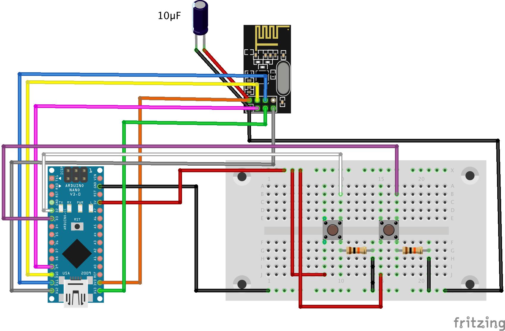
As you can make out from the sketch, I have connected the nRF24L01 in the same fashion as the controller, with the only difference being that I’ve used the Arduino Nano instead of the Uno.
Additionally, the circuit contains two push-buttons that send codes for arm and disarm signals. The pull-down resistors (10K ohms) are connected to ground, so these nodes are held low until a button is pressed which pulls the node high.
Programming the Panic Button Remote
The logic for programming the wireless panic button circuit is pretty straight-forward. We continuously read the state of both push-buttons (ARM/DISARM) in the loop() function and whenever we detect a HIGH state we send the corresponding code to the controller.
Here’s the code that you can simply copy-paste in your Arduino IDE (You’ll only need to change the paraphrase), and run it on your Arduino Nano:
#include <SPI.h>
#include <nRF24L01.h>
#include <RF24.h>
#include <RF24_config.h>
const int armButtonPin = 2; // the number of the arm button pin
const int disarmButtonPin = 3; // the number of the disarm button pin
int armButtonState = 0; // variable for reading the arm button status
int disarmButtonState = 0; // variable for reading the disarm button status
boolean armedStatus = false;
int msg[1];
RF24 radio(9,10);
const uint64_t pipe = 0xE8E8F0F0E1LL;
String passphrase = “YOURPASSPHRASE”;
String armMessage = passphrase;
String disarmMessage = passphrase;
void setup() {
Serial.begin(9600);
radio.begin();
radio.openWritingPipe(pipe);
// initialize the pushbutton pin as an input:
pinMode(armButtonPin, INPUT);
pinMode(disarmButtonPin, INPUT);
armMessage += “AA”;
disarmMessage += “BB”;
}
void loop() {
armButtonState = digitalRead(armButtonPin);
disarmButtonState = digitalRead(disarmButtonPin);
if (armButtonState == HIGH) {
for (int i = 0; i < armMessage.length(); i++) {
int charToSend[1];
charToSend[0] = armMessage.charAt(i);
radio.write(charToSend,1);
}
msg[0] = 2;
radio.write(msg,1);
radio.powerDown();
delay(1000);
radio.powerUp();
}
if (disarmButtonState == HIGH) {
for (int i = 0; i < disarmMessage.length(); i++) {
int charToSend[1];
charToSend[0] = disarmMessage.charAt(i);
radio.write(charToSend,1);
}
msg[0] = 2;
radio.write(msg,1);
radio.powerDown();
delay(1000);
radio.powerUp();
}
}
Integration Testing
Once the remote is up and functional, just try pressing the pushbutton on the remote circuit. If everything has been configured correctly, the buzzer will go off almost instantly and within a few seconds, you should really receive a text message on your smartphone.
You can now disable the alarm either from the remote or by sending the disarm paraphrase from your smartphone. Pretty cool, right?
Extra-features
While I laid down the basic infrastructure for a GSM-based alarm system, we can leapfrog on the existing setup, and make it more suitable for real-life applications by making a few improvements. Here’s how I plan on making the initial prototype more robust:
Run the setup on battery: It’s one thing to prototype a circuit on breadboard, and a completely different thing to make it suitable for day-to-day use.
For instance, our panic button alarm circuit draws about 10mA current, even in idle state. If we do the math, it would exhaust a standard 9V, 500mAh battery in about 50 hours. That’s a complete deal-breaker, right?
The power efficiency can be greatly improved by using a library that makes the Arduino sleep (JeeLib) when inactive and uses interrupts to wake it up. The details are out of the scope of this article, but in case you’re interested check out this video tutorial.
Use a loud alarm: I have used a piezo buzzer in this example, but it’s impractical to rely on its sound in real-life. So, the quickest way to solve that problem would be to simply replace the buzzer with a solid-state relay and connect a sufficiently loud siren to it.
Establish mesh networking: As an advanced feature, you can even think about linking motion or door sensors with the existing setup. But, in order to do that, you would require a mesh networking topology. The security controller would have to keep track of all nodes in the network and maintain the dynamic routing table, so that it knows the source of the signal.
For example, if the controller knows the node ID of the panic alarm button that you have placed in your basement, it could send you a much more detailed message, like, “Emergency alert from basement”, instead of just sending a panic message. The easiest library to get started with mesh networking is RF24Mesh.
Okay, I hope you found this tutorial to be helpful! If you have any questions or feedback please just leave it in the comments below and I’ll be sure to reply right away.

Hi John, i have tried numerous ways to get the control center code to indicate “module now actively listening to incoming messages” not sure what i am doing wrong. need your assistance.
Hi John
Thank you for such an amazing project. I am engineering student and I am trying out this project. However, I seem to have stumbled upon an issue. When I run the command “sudo ~/alexa-avs-sample-app/automated_install.sh” after the command “sudo chmod -R 777 /home/pi” I am getting the following errors:
[INFO] Scanning for projects…
[ERROR] [ERROR] Some problems were encountered while processing the POMs:
[ERROR] ‘dependencies.dependency.version’ for org.mortbay.jetty.alpn:alpn-boot:jar is missing. @ line 59, column 16
@
[ERROR] The build could not read 1 project -> [Help 1]
[ERROR]
[ERROR] The project com.amazon.alexa.avs:sample-java-client:20160207.8 (/home/pi/alexa-avs-sample-app/samples/javaclient/pom.xml) has 1 error
[ERROR] ‘dependencies.dependency.version’ for org.mortbay.jetty.alpn:alpn-boot:jar is missing. @ line 59, column 16
[ERROR]
[ERROR] To see the full stack trace of the errors, re-run Maven with the -e switch.
[ERROR] Re-run Maven using the -X switch to enable full debug logging.
[ERROR]
[ERROR] For more information about the errors and possible solutions, please read the following articles:
[ERROR] [Help 1] http://cwiki.apache.org/confluence/display/MAVEN/ProjectBuildingException
I am fairly new to Linux, can you please help me out?
I am getting this error
Not used: C:\Users\91949\Documents\Arduino\libraries\NRFLite
exit status 1
void value not ignored as it ought to be
Hello johan,
I am Remin, am searching for a project to check whether the motor is working or not, if not siren should raise wireless.
Hello jhon. I am wasantha .
I am getting a error on your code on line 122 as ,
exit status 1
Stary ‘\342’ in program
can you help me
Thanks
Hello jhon, Thank you for infos, but how do i install the RF library into the Arduino program which i installed on my c drive?
Hello thank you for this information as I am in the process of building a system for my home however I will use pir detectors along with the panic button with plans to add several cameras too. I will keep you posted again thanks
Thanks for sharing. I’m trying to build something slightly less complicated but cannot find an company or engineer to assist me. Can you point me in the right direction or any direction? Please and thank you!!
Hi Al,
Thanks for the comment! Please contact me directly at info@predictabledesigns.com and I’ll try to help you out.
Best wishes,
John
Thank you very much for sharing!
You’ve done a great job, and I am looking forward implementing it too to explore GSM!
Keep on like this.
Best regards,
Thanks Paul!
John
Very useful, it’s part of my free time projects that I will make real some day but using an old 68HC08 based card.
Thanks
Thanks for the feedback Jose! Let me know if I can ever help.
John