
From Raspberry Pi Prototype to Mass Production
Discover the various options that are available when transitioning from a Raspberry Pi prototype to a custom PCB design for mass production.
The Raspberry Pi is far and away one of the most popular and accessible solutions for adding embedded Linux to a project.
Its ubiquity, purpose-built operating system, and a wealth of online support makes it an excellent choice for a product’s prototype.
Prototypes built using a Raspberry Pi are also simple to construct.
Both the standard and Zero variants of the Pi have mounting holes and 2.54mm pin headers for easily mounting into a case and connecting to external sensors and other devices.
The trouble with these kinds of prototypes is that they are generally large, bulky, and are not straightforward to assemble.
This doesn’t mean that using the standard or Zero versions of a Pi can never be used for a manufacturable product.
For the right applications, there may not be any downsides to using them.
However, the focus of this article will be taking a Raspberry Pi to a deeply embedded application, on a custom PCB where size is at a premium.
For these applications, the Raspberry Pi Foundation offers Compute Modules, which are boards containing the same processors, memory, and I/O as certain standard Raspberry Pi boards.
But, they are in a form factor that is not designed to be standalone, but rather to fit into a larger circuit board through various mounting techniques.
Raspberry Pi Compute Module 3+
The last-generation Raspberry Pi Compute Module 3+ shown in Figure 1, for example, was in a DDR2 SODIMM form factor.
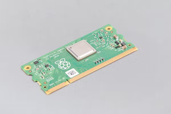
Figure 1 – Raspberry Pi CM3 +, a refactored Raspberry Pi 3 Model B+
To directly quote the CM3+ product page: “The CM3+ Compute Module contains the guts of a Raspberry Pi 3 Model B+ (the BCM2837 processor and 1GB RAM) as well as an optional eMMC Flash device of 8GB, 16GB or 32GB (which is the equivalent of the SD card in the Pi).”
What this means for a product developer is that, from a software standpoint, you can expect essentially identical performance from their application when porting to the CM3+ if they were using a Raspberry Pi 3 Model B+ (or something weaker) in their prototype.
From a hardware perspective, the CM3+ is an upgrade in many respects – most notably, when looking at the datasheet we can see that it has 46 GPIO pins.
This is compared to the 26 available on the 3B+ board, which is a virtue of the embedded form factor allowing for much greater density in the breakout from the Broadcom BCM2837 processor.
It also comes with extra digital peripherals like SPI, I2C, and UART buses available. Additionally, the CM3+ offers a variety of storage options to choose from.
For ultra-compact applications, it can be purchased with onboard eMMC flash memory in size of 8-32GB.
There is also a “Lite” option that does not come with onboard memory. Therefore, it must be provided externally in the form of an SD card on the PCB it will be mounted on.
Note that as large companies like Tesla have shown, eMMC flash is non-removable and is thus not recommended for projects that will see heavy or long-term use of storage.
Products with those requirements should consider leaning towards the Lite option for their projects.
Raspberry Pi Compute Module 4
A more modern option for Compute Modules is the CM4, which like the CM3+ is a compact refresh of a standard Raspberry PI model, this time the 4.
While it has more modern and performative specs like a quad-core Cortex-A72 ARM processor and a multitude of onboard wireless options, it retains the same principle of the CM3+.
It has more GPIO compared to the original board it is based on, and a flexible form factor with a variety of options to choose from.
In fact, it has 32 variants in total counting all wireless, RAM, and storage combinations!
These modules offer performance beyond the standard RPi board used for early prototyping.
But since these modules cannot be used on their own, how can you test this extra functionality for your product without going through a time-consuming and costly PCB design?
Compute Module I/O Boards
Raspberry Pi again provides the solution for this in the form of I/O boards like the one for the CM4.
These I/O boards first and foremost provide a motherboard on which to mount the compute module and power it on so that it can be used.
It also provides all the I/O that someone used to a regular Raspberry Pi would expect such as HDMI, Ethernet, USB, etc.
The I/O board thus effectively turns a compute module into a fully functioning Raspberry Pi board ready to use in a prototyping application.
If you are looking to use a compute module in a manufacturable product and have the time to do so, it is highly recommended to make your first step transferring your working prototype to a CM I/O board, and re-verifying functionality there.
If possible, the best-case scenario is to start with an I/O board for your prototype from the beginning.
But you will need to plan far enough in advance to know that you will need a compute module for the final product.
However, as previously stated, the compute modules are for the most part functional supersets of their standard board complements.
So, any prototype that you already have should transfer fine to a compute module and by extension its I/O board.
The most significant benefit of the I/O boards, however, is the fact that their ECAD files or reference schematics are available on their product pages.
The CM4 I/O board, for example, links to a downloadable KiCAD project for itself, so that users can manufacture the I/O boards for themselves.
More importantly the design files allow you to reference a verified, working example of a motherboard for the CM4.
This is beneficial because the number of I/O pins available on compute modules, and the external components required for their proper operation, are numerous and complex compared to standard Pis.
Sifting through the datasheets and reference manuals to come up with a board design from scratch is no easy task.
The schematic and parts were selected by the same organization which designed the compute module itself.
There are thousands upon thousands of individuals and groups who have successfully implemented the I/O board and verified its functionality.
Perhaps one of the most useful contributions from this design is a voltage regulator complete with a working circuit that can power the CM4 from a 5V or12V supply.
An additional pain is that typically it takes a long time for symbols/footprints for these compute modules, as well as supporting connectors and parts, to show up in standard libraries for ECAD programs.
At this time, for example, only CM symbols up to the CM3+ are available in the standard KiCAD symbol libraries (at least, on the writer’s installation).
The I/O board provides symbols and footprints for the CM socket and many obscure supporting parts like the camera sockets that are known to work.
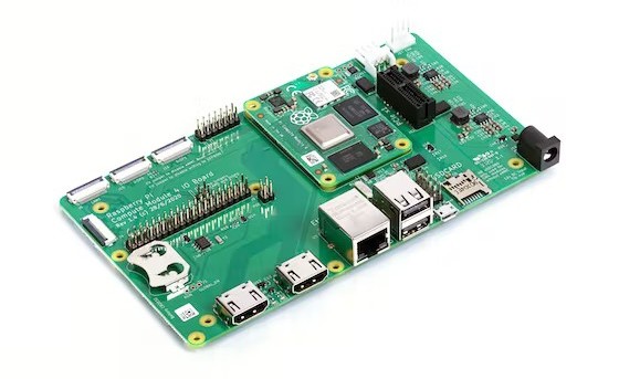
Figure 2 – The I/O board for the CM4. Note the dual HDMI and the SD card slot for the Lite variants.
Reference Designs
An alternative to simply using the I/O board schematic and/or design files as only a reference and source of ECAD libraries, is to literally use it as a base for your design.
I myself have begun more than one CM4-based project by simply downloading the board files and modifying them to suit my needs.
I started by stripping off any I/O that I wasn’t using, replacing certain connectors with others, etc.
Another option, if you have an existing board design using KiCAD, is to drop the necessary schematic files from the CM4 into your design as sub-sheets.
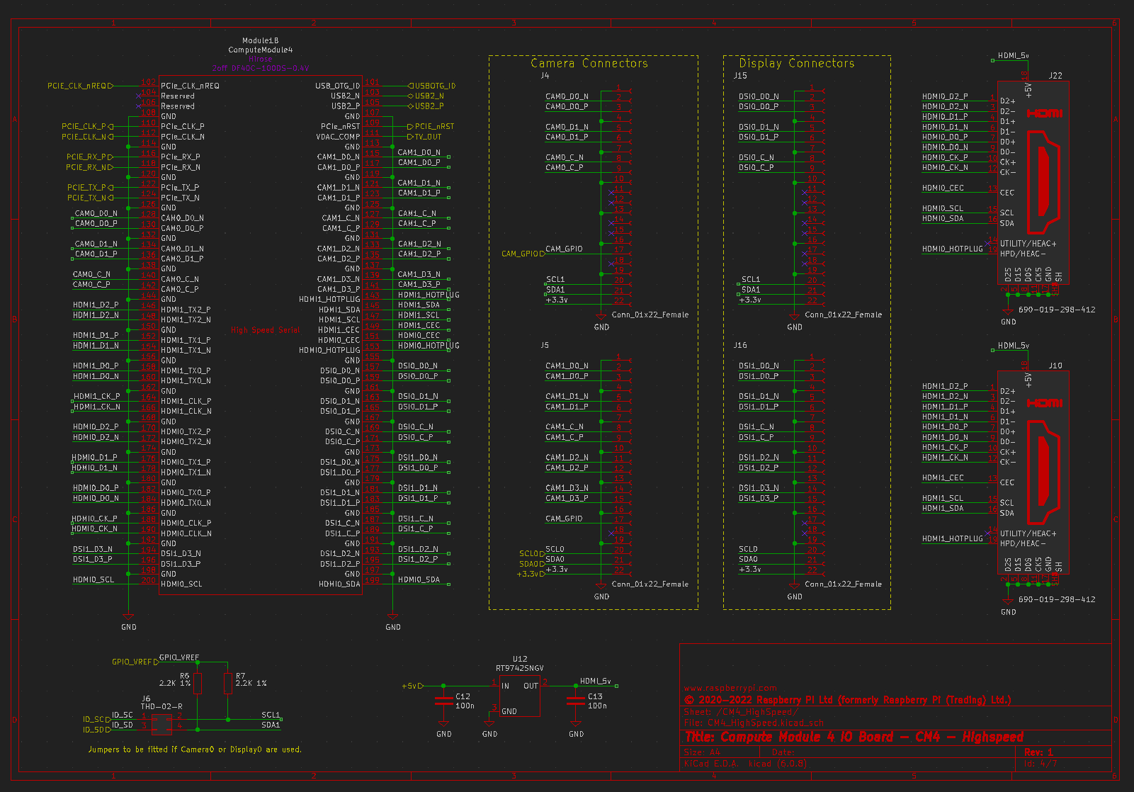
Figure 3 – The core schematic sheet of the CM4IO board containing the CM4 itself.
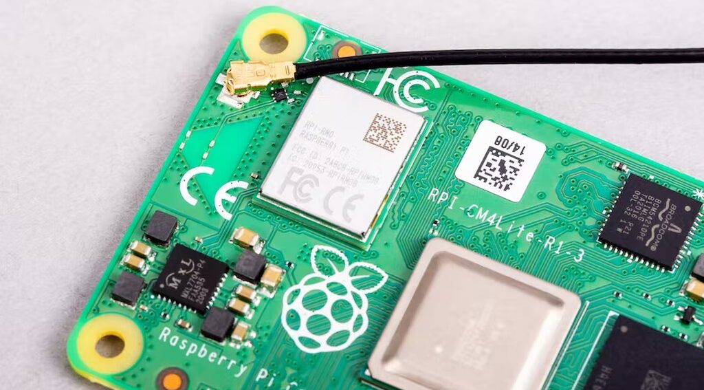
Wireless Connectivity
A common concern with compacted form factors is that wireless capability will be hampered.
While the CM4 does have a built-in antenna in the form of a PCB trace, it also provides a switch on the module that allows using an external antenna instead.
You can purchase a certified external antenna from the Raspberry Pi website here.
Another concern associated with wireless connectivity, particularly for devices based upon custom PCBs, is licensing and certification.
The benefit of having wireless functionality baked into the module itself is that much of the work involved with obtaining RF certifications has already been done for you.
Guides are provided to complete the certification processes for 3rd party tests should your product make use of the Bluetooth or WiFi capabilities of the CM4.
Setup Process for Compute Module 4
When it comes to setting up a new CM4, the process can follow a normal Raspberry Pi’s if some conditions are met, otherwise some special tools are required.
First, if you have chosen the Lite version of the CM4 and your motherboard has an SD card slot, you can simply copy standard Raspberry Pi OS to the SD card as you would for a regular Raspberry Pi 4.
Just insert it into the slot, and power on the CM4. No further action is required since, as we mentioned, the CM4 uses the exact same processor as the Raspberry Pi 4.
Without an onboard SD card, the process gets trickier. You will need a micro-USB port that is connected to the CM4 in the same manner that the J11 connector is on the I/O board.
This obviously requires that your custom board design has a micro-USB port on it.
Additionally, there is a jumper on the I/O board that must be shorted during the setup process that prevents the CM4 from trying to boot from the eMMC, which won’t have any valid data on it when it first arrives to you.
From there the steps outlined in this guide can be followed to install the software required to initialize the eMMC as a valid storage device, and subsequently load an operating system on it.
Note that when following this process, there will be many peripherals, including USB, that will be disabled when flashing is complete.
This is a common practice in this sort of deeply embedded device, but due to the general similarity to the Raspberry Pi 4 some users may not be aware of this.
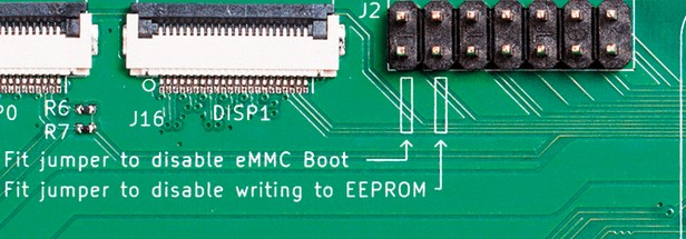
Figure 4 – The I/O board jumper that needs to be shorted during setup.
Having common I/O like the eMMC jumper, a micro-USB port and mini-HDMI is very helpful to have on a custom board for easier development and debugging, but this is frequently not possible for small devices.
For this reason, it is a good idea to have an official I/O board on hand whenever working with a Compute Module, even if it was not used for prototyping.
This is because it can be used to both setup a compute module and to debug it independently from your custom board design.
Additionally, opting for the wireless version of the CM4 for the sole purpose of SSH is highly recommended, especially during the development phase and if your custom board lacks video I/O.
Being able to get a shell on your device while it is fully assembled and mounted on the custom board will speed up the development process immensely and has no impact on the size of the device.
Alternatively, doing development of a non-wireless product with some wireless CM4s and then switching to non-wireless in the later stages is a great way to have your cake and eat it too.
You get the ease of development that comes with SSH access to your embedded device, while saving $5 a unit when it comes to development, since you can just drop in the non-wireless CM4s.
For more advanced developers, the Raspberry Pi foundation provides a wealth of information about the CM4 boot process and device tree, making it easier to run custom embedded Linux applications on the device.
The flexibility and support that come with Raspberry Pi Compute Modules make them an attractive choice for those looking to take their Raspberry Pi project to the manufacturing stage.
