
Charging Methods for Lithium-Ion Batteries
The battery type of choice for most electronic products that run on batteries is the li-ion battery. Discover what it takes to charge them properly.

Li-ion is the battery most commonly used in consumer electronics products. Of the other types that were used previously, NiCad batteries for use in electronic equipment have been banned in the EU, so the overall demand for those types have dropped.
NiMH batteries are still used, but their lower energy density and cost to benefit ratio make them unattractive.
Li-ion battery operation and construction
Li-ion batteries are considered secondary batteries, meaning they are rechargeable. The most common type consists of an anode made of a graphite layer coated on a copper substrate, or current collector, and a cathode of lithium cobalt oxide coating on an aluminum substrate.
The separator is typically a thin polyethylene or polypropylene film that electrically separates the two electrodes, but allows the transport of lithium ions through it. This arrangement is shown in figure 1.
Various other types of anode and cathode materials are also used, the most common cathodes typically lend their names to the type description of the battery.
Thus, lithium cobalt oxide cathode cells are known as LCO cells. Lithium nickel manganese cobalt oxide types are referred to as NMC types, and cells with lithium iron phosphate cathodes are known as LFP cells.
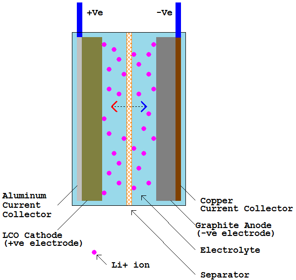
Figure 1 – Major components of a typical li-ion cell
In an actual li-ion cell, these layers are typically tightly wound together, and the electrolyte, while liquid, is barely enough to wet the electrodes, and there is no liquid sloshing around inside.
This arrangement is shown in figure 2, which depicts the actual internal construction of a prismatic, or rectangular metal case, cell. Other popular case types are cylindrical and pouch (commonly referred to as polymer cells).
Not shown in this figure are the metal tabs that are attached to each current collector. These tabs are the electrical connections to the battery, essentially the battery terminals.
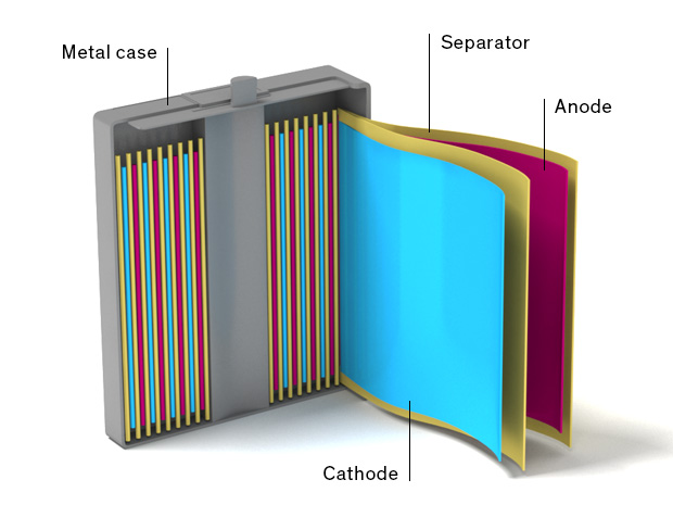
Figure 2 – Typical internal construction of a prismatic li-ion cell
Charging a li-ion cell involves using an external energy source to drive positively charged li-ions from the cathode to the anode electrode. Thus, the cathode becomes negatively charged, and the anode positively charged.
Externally, charging involves movement of electrons from the anode side to the charging source, and the same number of electrons being pushed into the cathode. This is the opposite direction to the internal flow of the li-ions.
During discharge, an external load is connected across the battery terminals. Li-ions that were stored in the anode move back to the cathode. Externally, this involves movement of electrons from the cathode to the anode. Thus, an electric current flows through the load.
Briefly, what is happening inside the cell during charging, for example, is that at the cathode side, the lithium cobalt oxide gives up some of its lithium ions, becoming a compound with less lithium that is still chemically stable.
At the anode side, these lithium ions embed, or intercalate, in the interstitial spaces of the graphite molecular lattice.
Several issues have to be considered during charging and discharging. Internally, the li-ions have to cross several interfaces during charging and discharging. For example, during charging, the li-ions have to transport from the bulk of the cathode to the cathode to electrolyte interface.
From there it has to move through the electrolyte, through the separator to the interface between electrolyte and anode. Finally, it has to diffuse from this interface to the bulk of the anode material.
The rate of charge transport through each of these different media is governed by its ionic mobility. This, in turn, is affected by such factors as temperature and ion concentration.
What this means in practice is that precautions have to be taken during charging and discharging to ensure that these limitations are not exceeded.
Li-ion battery charging considerations
Charging li-ion batteries requires a special charging algorithm. This is carried out in several stages described below:
Trickle charge (Pre-charge)
If the battery charge level is very low, then it is charged at a reduced constant current rate that is typically around 1/10 the full-rate charging rate described next.
During this time, the battery voltage increases, and when it has reached a given threshold, the rate of charge is increased to the full charge rate.
Note that some chargers break down this trickle charge stage into two: pre-charge and trickle charge, depending on how low the battery voltage is initially.
Full rate charge
If the battery voltage is initially high enough, or if the battery has charged up to this point, then the full charge rate stage is initiated.
This is also a constant current charging stage, and during this stage the battery voltage continues to slowly rise.
Taper charge
When the battery voltage has risen to its maximum charge voltage, the taper charge stage begins. In this stage, the charging voltage is kept constant.
This is important as li-ion batteries will fail catastrophically if allowed to charge at a higher voltage than their maximum voltage. If this charging voltage is kept constant at this maximum value, then the charging current will slowly decrease.
Cutoff / Termination
When the charging current has decreased to a low enough value, the charger disconnects from the battery. This value is typically 1/10, or 1/20, of the full-rate charge current.
It is important not to float charge li-ion batteries as this will reduce the performance and reliability of the battery in the long term.
While the previous section describes the various charging stages, specific threshold values for the various stages were not provided. Starting with the voltage, each li-ion battery type has its own full charge terminal voltage.
For the most common LCO and NCM types, that’s 4.20V. There are some with 4.35V and 4.45V as well.
For LFP types, it is 3.65V. The trickle charge to full charge threshold is around 3.0 and 2.6 for LCO/NMC, and LFP types respectively.
A charger that is designed to charge one type of li-ion battery, such as LCO, cannot be used to charge another type such as an LFP battery.
Note, however, that there are chargers that can be configured to charge multiple types. These typically require different component values in the charger design to accommodate each type of batteries.
When it comes to the charging current, a bit of explanation is required. Li-ion battery capacity is traditionally reported as mAh, or milliAmps-Hour, or Ah. This unit, in itself, is not actually a unit of energy storage capacity. To get to an actual energy capacity, the battery voltage has to be considered.
Figure 3 shows a typical discharge curve for an LCO type li-ion battery. Since the discharge voltage has a slope, the average battery voltage of the entire discharge curve is taken to be the battery voltage.
This value is typically 3.7 to 3.85V for LCO types, and 2.6V for LFP types. Multiplying the mAh value with the average voltage of the battery then yields the mWh, or energy storage capacity, of a given battery.
Battery charging current is given in terms of C-rate, where 1C is numerically the same as the battery capacity in mA. Thus, a 1000mAh battery has a C value of 1000mA. For various reasons, the maximum charging rate allowed for a li-ion battery is typically between 0.5C and 1C for LCO types, and 3C, or more, for LFP types.
A battery can, of course, consist of a minimum of one cell, but may consist of many cells in a combination of series-connected groups of parallel-connected cells.
The scenario given previously applies to single-cell batteries. In cases where the battery consists of multiple cells, the charging voltage and charging current have to be scaled to match.
Thus, the charging voltage is multiplied by the number of series connected cells, or group of cells, and, similarly, the charging current is multiplied by the number of parallel-connected cells in each series-connected group.
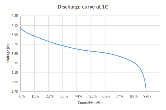
Figure 3 – Typical discharge curve of an LCO-type battery
One very important additional factor that has to be considered when charging li-ion batteries is temperature. Li-ion batteries cannot be charged at low or high temperatures.
At low temperatures, the li-ions move slowly. This can cause the li-ions to bunch up at the surface of the anode where they will eventually turn into lithium metal. Because this lithium metal formation takes the form of dendrites, it may pierce the separator, causing internal shorts.
On the high end of the temperature range, the problem is excess heat generation. Battery charging is not 100% efficient, and heat is generated during charging. If the internal temperature of the core gets too high, the electrolyte may partially decompose, and turn into gaseous by-products. This causes a permanent reduction in the battery capacity as well as swelling.
The typical temperature range for charging li-ion batteries is 0°C to 45°C for high quality batteries, or about 8°C to 45°C for cheaper batteries. Some batteries also allow charging at higher temperatures, up to about 60°C, but at reduced charging rates.
All of these considerations are typically fulfilled by dedicated charger chips, and it is highly recommended to use such chips regardless of the actual charging source.
Li-ion chargers
Li-ion chargers broadly fall into two main categories: linear and switching chargers. Both types can fulfill the requirements previously stated regarding the proper charging of li-ion batteries. However, they each have their advantages and disadvantages.
The advantage of a linear charger is its relative simplicity. However, its main drawback is its inefficiency. For example, if the supply voltage is 5V, the battery voltage is at 3V, and the charging current is 1A, the linear charger will be dissipating 2W.
If this charger is embedded in a product, that’s a lot of heat that will have to be dissipated. That is why linear chargers are mostly used in cases where the maximum charging current is about 1A.
For large batteries, switching chargers are preferred. They can have efficiency levels of up to 90% in some cases. Disadvantages are its higher cost and the somewhat larger circuit real estate requirements due to the use of inductors in its design.
Charging source consideration
Different applications can call for different charging sources. For example, this can be a straight AC Adapter that provides a DC output, or a power bank. It could also be a USB port from a desktop or similar appliances. It could also be from a solar panel assembly.
Because of the power delivery capabilities of these different sources, further consideration must be given to the design of the actual battery charger circuit besides simply choosing a linear or a switching charger.
The most straightforward case is when the charging source delivers a regulated DC output such as an AC Adapter or a power bank. The only requirement is choosing a charging current that does not exceed the battery maximum charging rate, or the source power delivery capability.
Charging form a USB source requires a bit more attention. If the USB port is a USB 2.0 type, then it will be following the USB Battery Charging standard 1.2, or BC 1.2.
This requires that any load, in this case the battery charger, should not take more than 100 mA unless the load has enumerated with the source. In this case, it is allowed to take 500mA at 5V.
If the USB port is USB 3.1, then it can follow USB BC1.2, or an active controller circuit can be incorporated in the design to negotiate for more power following the USB Power Delivery, or USB PD, protocol.
Solar cells as a charging source present another set of challenges. A solar cell Voltage-Current, or VI, is somewhat similar to that of a regular diode. A regular diode will not conduct any appreciable current below its minimum forward voltage value, and then can pass much larger current with only a slight increase in the forward voltage.
A solar cell, on the other hand, can supply current until a certain maximum at a relatively flat voltage. Beyond that current value, the voltage drops sharply.
So, a solar charger has to have a power management circuit that modulates the current drawn from the solar cell so as not to cause the output voltage to go too low.
Fortunately, there are chips such as the TI BQ2407x, BQ24295, and others, that can accommodate one of more of the above sources.
It is highly recommended to spend the time to search for an appropriate charging chip rather than designing a battery charger from scratch.
