
Introduction to Basic Electronic Circuits
This article is an introduction to very simple electronic circuits. I’ve kept this introductory article as simple as possible for readers that are new to electronics.

In a previous article we reviewed all of the various electronic components and how they work.
But to be of any real use electronic components have to be connected together to form electronic circuits.
There are some equations in this article but please don’t let those scare you away. The equations used are all relatively easy to understand and they will help give you a more fundamental understanding of the circuit being discussed.
Resistor circuit
We’re going to start off by looking at the simplest circuit possible and that is a circuit that only includes a voltage source and a resistor (Figure 1).
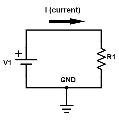
Figure 1 – Simple resistor circuit
The voltage source symbol shown is a battery, but any DC power source could be substituted. The current which is represented by “I”, with the arrow shown, will flow from the positive terminal of the voltage source V1 through the wire, down through R1 and then into ground.
The most fundamental equation in all of electronics is Ohm’s Law. Ohm’s Law is just a simple equation that shows how voltage, current, and resistance are all related. Using a little algebra Ohm’s Law can be written in three forms:
I = V / R
V = I * R
R = V / I
where I = current in amps, V = voltage in volts, and R = resistance in ohms. For example, if V1 = 3V and R = 1kohm, then the current flowing will be 3V / 1kohm = 3 mA. Increasing the voltage or decreasing the resistance both act to increase the current flowing.
Resistor divider
The next circuit that we’re going to look at is called a resistor divider. The simplest type of resistor divider is made up of just two resistors. As the name implies, a resistor divider provides a simple method of accurately dividing down a voltage.
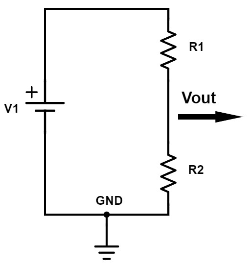
Figure 2- Resistor divider circuit
The equation to calculate the output voltage of a resistor divider is:
Vout = [ R2 / (R1+R2) ] * Vin
As this equation shows the output voltage is proportional to the ratio of R1 and R2.
Let’s look at a couple of simple cases. A lot of times when you’re wanting to understand a mathematical equation it’s good to look at some of the extreme limits. This can help give you a better understanding of the equation as well as provide a check if the equation is correct.
I’m going to look at three different possibilities that will make it easier to visualize:
Case #1: R1 = 0, R2 > 0
If R1 becomes zero ohms, then that’s a short. That would mean V1 is shorted directly to the output. It doesn’t really matter what R2 is as long as it’s not a short.
In this case, the resistor divider equation simplifies down to
Vout = [ R2 / (0 + R2) ] * Vin
Vout = Vin
There is no voltage division and the output voltage simply equals the input voltage.
Case #2: R1 > 0, R2 = 0
If R2 = 0 (short) and R1 is anything above 0 ohms, then in that case, the output is simply shorted to ground. For this case, the equation simplifies as follows:
Vout = [ 0 / (R1+0) ] * Vin
Vout = 0 * Vin = 0
Case #3: R1 = R2
If you make R1 and R2 equal then the equation simplifies down to:
Vout = [ R2 / (R2 + R2) ] * Vin
Vout = [ 1 / 2 ] * Vin
So in the case of R1 and R2 being equal then the output voltage of a resistor divider will be exactly half of the input voltage.
Capacitor circuit
The next circuit that we’re going to look at is a voltage source and a capacitor.
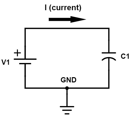
Figure 3 – Simple capacitor circuit
The instantaneous current through a capacitor depends on the rate at which the voltage across that capacitor changes. The equation for the current through a capacitor is as follows:
i = C * dv / dt
In this equation “i” equals the current through the capacitor (a lower case letter is typically used to indicate an instantaneous parameter that changes with time, not a DC value). “C” is the capacitance in Farads and dv/dt indicates the rate at which the voltage across the capacitor changes with time.
Let’s assume that when the voltage source is first turned on it ramps up from 0 volts to 3 volts in 1 second. That would be a ramp rate (dv/dt) of 3V/s. To calculate the instantaneous capacitor current you then simply multiply this ramp rate by the capacitance.
When a capacitor is fully charged it looks like an open circuit to DC current so no current will flow. When there is a stable DC voltage across a capacitor the dv/dt factor in the equation above becomes zero since the voltage isn’t changing with time.
But briefly, before the capacitor is charged, it looks like a short circuit (or low impedance). If you set the dt term in the equation to zero (for zero time) the current approaches infinity which just means a short circuit.
When the circuit shown in Figure 3 is first powered on, the capacitor looks like a short because the capacitor isn’t charged yet. In reality, it won’t be a true short circuit, because the voltage source, the circuit trace, and the capacitor all have small amounts of parasitic resistance.
Once the voltage source reaches its final voltage, and the capacitor is fully charged, the current will stop flowing (other than a small amount of leakage current). This is because the voltage ramp rate (dv/dt) is now zero.
The current flows only while the voltage source is ramping up, and this equation allows you to calculate the current through that capacitor during this ramp up process.
Capacitor in series versus parallel
We’re going to look at two more simple capacitor circuits, just to help you have a better grasp on how capacitors can operate.
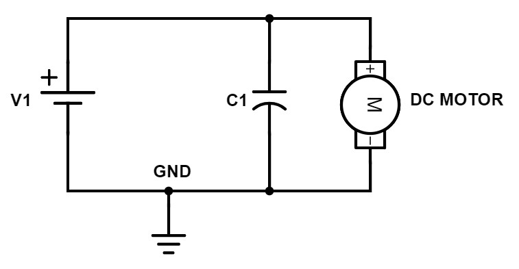
Figure 4 – Capacitor with motor in parallel
In this circuit, we have a voltage source in parallel with the capacitor in parallel with a DC motor. The motor isn’t really important for what we’re discussing here and this could be anything from a microcontroller to a voltage regulator.
In this case, the full voltage of V1 gets delivered to the motor. Once the capacitor becomes charged, all of the current will flow through the motor.
Now, if we change that circuit and instead of putting the motor in parallel with C1 and V1, let’s put them all in series together.
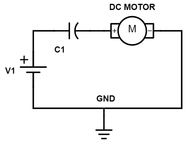
Figure 5 – Capacitor with motor in series
In this case, the motor may actually run very briefly while the voltage source is ramping up, but as soon as V1 reaches its final voltage and C1 becomes charged, no current will flow through the motor. So in this circuit the motor would likely not operate as intended.
Diode circuits
Now we are going to look at the circuit consisting of a voltage source, a resistor and a diode, all in series together. Essentially, a diode allows current to flow through it in only one direction (if you need a refresher on diodes and transistors see Introduction to Basic Electronics).
Forward-biased diode
The symbol for a diode looks like an arrow that’s pointing in the direction that current is allowed to flow. If a diode is oriented in a circuit to allow current to flow through it then that diode is forward-biased.
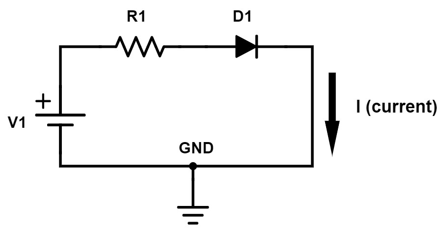
Figure 6 – Forward-biased diode circuit
If you want to calculate the current that flows through the diode shown in Figure 6, you would use Ohm’s Law. However, you have to do something a little bit different because of the diode.
When forward-biased a diode has approximately a fixed voltage drop across it, which is usually about 0.7V. But, there are many different types of diodes all with slightly different voltage drops. For example, a type of diode called a Schottky diode has a voltage drop closer to 0.5V.
To calculate the current flowing in this circuit you must figure out the voltage across R1. The purpose of this resistor is to set and limit the current for this circuit.
The very first circuit we looked at only had a voltage source and a resistor. The full voltage source was applied across the resistor because the other end of the resistor tied to ground.
That’s not the case here because this other terminal of the resistor is tied to the diode, not to ground. That means the voltage drop across the diode reduces the amount of voltage across the resistor. The voltage across the resistor is equal to V1 – 0.7V.
The equation to calculate the current for this circuit is:
I = (V1 – 0.7) / R
For example, if the voltage source is 3V and the resistor is 1kohm then the current will be (3 – 0.7) / 1k = 2.3 / 1k = 2.3 mA
Reverse-biased diode
This next circuit looks identical except the diode is facing the opposite direction. Because of the polarity of the voltage source the current once again wants to flow in the direction of the arrow but the diode is now reverse-biased.
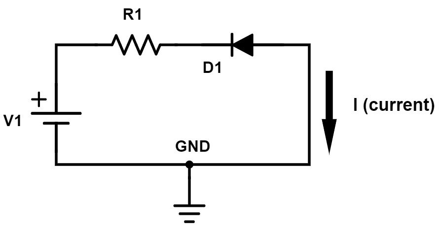
Figure 7 – Reverse-biased diode circuit
This circuit is really easy to analyze because no current will flow with the diode reverse-biased.
Nothing is ever perfect though, and there is always a small amount of leakage current that will flow through a reverse-biased diode. Also, if V1 were to exceed the diode’s maximum reverse-bias voltage rating then the diode may become damaged allowing current to flow.
Light Emitting Diode (LED)
We’re going to look at one more diode circuit. This circuit is just like the forward-biased diode circuit that we looked at above. However, instead of just a normal diode, this circuit uses a special type of diode called a Light Emitting Diode (LED).
As the name implies, an LED emits light when current passes through it while forward-biased. An LED also still acts as a normal diode and only allows current to flow in one direction.
Figure 8 – Simple LED circuit
If you put this diode in backwards and it is reverse biased then no current will flow and no light will be produced. The amount of light that’s emitted by an LED depends on the current flowing through it, not the voltage across it.
To calculate the current for this circuit you would do exactly as done for the forward-biased diode circuit discussed earlier using the equation I = (V1-VD)/R where VD is the diode voltage.
Be aware though that the forward voltage drop of an LED can vary drastically depending on the color of the LED and will likely be higher than 0.7V.
Filter circuits
Now we’re going to look at filter circuits designed to pass and/or reject particular frequencies. Filters are one of the most important and fundamental circuits that have an almost endless number of applications.
You can have, for instance, a low-pass filter that passes low frequency signals, but rejects higher frequencies. A high-pass filter does just the opposite. It passes the high frequencies and blocks the low frequencies.
A band-pass filter will only pass frequencies within a certain range. Finally, a notch filter will reject frequencies within a specific range, and pass all frequencies outside of that range.
Frequency is measured in cycles per second or Hertz. For example, human hearing reaches up to around 10-20 kHz (10-20 thousand times per second). A Bluetooth or WiFi radio signal at the other extreme oscillates at a frequency of 2.4 GHz (2.4 billion times per second).
Low-pass RC filter
The simplest low-pass filter is made using only a resistor and a capacitor and is appropriately called an RC filter.
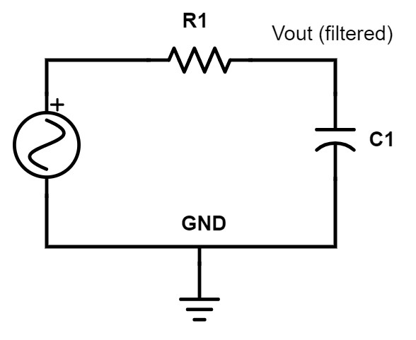
Figure 9 – Low-pass RC filter
In this circuit, the signal goes into R1 and the filtered output is taken off the node between R1 and C1.
A capacitor passes high frequencies and blocks low frequencies. So in a low-pass RC filter, low frequencies will see C1 as very high impedance (open-circuit), and high-frequencies will see the capacitor as low impedance to ground.
In a low-pass RC filter, all the high frequencies go through C1 to ground. This essentially removes the high-frequency components, whereas low frequencies are passed on to the output.
The cutoff frequency is the frequency at which the filter begins filtering. For a low-pass filter, frequencies below the cutoff frequency are passed, and those above the cutoff frequency are rejected.
No filter is perfect though, and there will be some frequencies around the cutoff frequency that are passed to the output highly attenuated (reduced).
The equation to calculate the cutoff frequency for an RC filter is:
F = 1 / (2 * PI * R * C)
What sets the cutoff frequency is essentially R times C. The factor R *C is commonly called the time constant of the filter.
High-pass RC filter
For the high-pass RC filter we simply swap the resistor and the capacitor. The capacitor is still a high impedance to low frequencies and a low impedance to high frequencies.
But by swapping the two components the low-frequencies are now blocked by the capacitor (they don’t pass through C1 to the output), whereas the high frequencies are allowed to pass to the output.
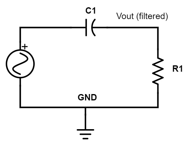
Figure 10 – High-pass RC filter
The cutoff frequency follows the exact same equation as the low-pass RC filter, except that now frequencies above this cutoff frequency are passed. Hence, the name high-pass filter.
Low-pass LC filter
The next step up from RC filters are LC filters where the resistor is replaced with an inductor. An inductor functions just the opposite from a capacitor. An inductor passes low frequencies, and blocks high frequencies.
For an RC filter the resistor simply sets the cutoff frequency. If there is no resistor, the cutoff frequency becomes infinite – meaning every frequency is passed and no filtering at all occurs. For a simple RC filter, it’s only the impedance of capacitor that changes with frequency and performs the filtering.
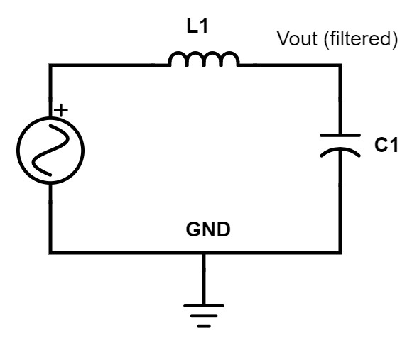
Figure 11 – Low-pass LC filter
On the other hand, with an LC filter both components contribute to the filtering. For a low-pass LC filter, in addition to the capacitor sending high frequencies to ground, high frequencies are also blocked by the inductor from reaching the output.
So for low frequencies, L1 looks like a short, and the C1 like an open circuit, therefore passing those frequencies on to the output unattenuated.
For high frequencies the L1 looks like an open, and the C1 looks like a short to ground, therefore no high frequencies will be passed along to the output.
The equation for the cutoff frequency of an LC filter is similar to an RC filter except instead of simply R * C the factor becomes the square-root of L * C.
F = 1 / [ 2 * PI * SQRT(L * C) ]
High-pass LC filter
Just as we did for the high-pass RC filter, for the high-pass LC filter we simply swap the positions of the inductor and the capacitor.
Now the capacitor blocks low-frequencies and passes high-frequencies, while the inductor sends low-frequencies to ground. Therefore, only frequencies above the cutoff frequency will pass on to the output.
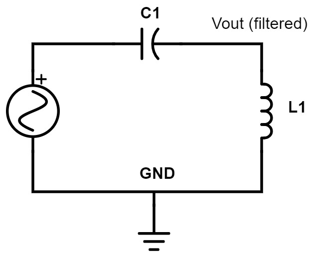
Figure 12 – High-pass LC filter
Conclusion
You are now well on your way to understanding the basics of how electronic circuits operate. I’ve purposely kept this introductory article rather simple so as not to overwhelm you.
But this article gives you the foundation you need to begin learning more advanced electronic circuits. The circuits we’ve looked at in this introductory article don’t provide much independent functionality but they will be used as building blocks within countless circuits.

Hi john please tell me that when the DC power is given to the circuit the decoupling capacitor becomes short means it draws more current. How this taken care in the circuit. Because no resistor will be used output of the regulator to avoid short circuit.
This is such a nice information about the the circuit and resistors. Thank You
Actually, the current arrows should be reversed! Electrons flow from negative to positive.
That is true but no one analyzes circuits using that direction.
Well done John. Feels the nostalgic memories of my class days. I have sent this link to my daughter pursuing her degree in computer engineering. It helps her a lot to grasp the basics in a simple way. As BJ suggest it would be better to explain the circuts with real world examples especially in finding input/output impeadence of transistor circuits
Warm Regards
Jay
Thank you so much Jay! I’m glad you have found it helpful.
Very useful to revise basics.
Hi John
Excellent articles for newbie like me! Keep it up!
One request: Seems the link to the PDF of your previous article “Introduction to Basic Electronics” might be broken as I sent the request twice and nothing happened.
One suggestion: In this article, if you could provide a real world example of where and why would one want to use a particular component in a circuit, it would be a big help to those of us who are trying to ‘do something’ with a circuit. Without that, its all very abstract and wonder” where could I use this to solve my particular problem?”
Thanks in advance!
BJ
Thank you BJ for the positive feedback and suggestion.
The PDF download link is working fine for me. Did you check your Promotions tab in gmail? I assume you got to the point where you enter your email? If still no luck email me at info@predictabledesigns.com.
Great suggestion and I will try to give more real world examples.
Thanks,
John
Nice run-through! Hope all is well, John.
-Casey
Thanks for the feedback!