
Product Teardown: LandAirSea 54 GPS Tracker
Product teardowns are one of the best ways to learn product development. In this article, we will tear apart a real-time GPS tracker by LandAirSea to see what it took to develop.
Battery-powered, wireless devices are a type of hardware product that is more and more in demand as the IoT market expands and evolves, so understanding how they work is important.
We’ll also take a look at the considerations that companies make when developing these kinds of products.
Some of this device’s key features include:
- A waterproof enclosure
- A strong magnet to allow it to stick to cars and other metal surfaces
- 4G LTE for real-time wireless transmission of location (with a subscription)
This wireless capability will also enable you to see how a product containing two fairly complex and high-range forms of wireless communication (LTE and GPS) is constructed and what sort of parts were chosen with FCC certifications in mind.
Inside the box there are four items: the device itself (pictured below), a micro-USB charging cable, an extra rubber cover for the charging port, and a small metal tool for pressing the pinhole on/off button, which was a nice addition.
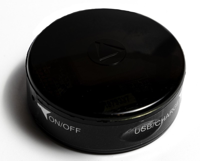
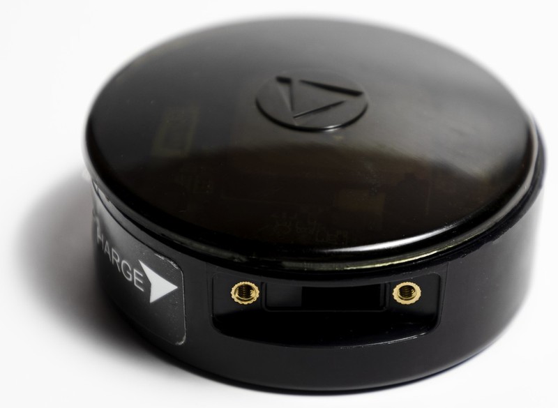
As expected, the device exterior is fairly plain, with a minimal logo on the top, a sticker pointing to the on/off button and charging port on the side, and a larger sticker on the button with the serial number and some technical info.
As alluded to above, there is a removable piece of rubber covering the micro-USB device charging port.
However, beyond that there are no removable parts or external screws to be seen, making the initial approach to the teardown a bit unclear.
With a little effort and a prying tool, though, it turns out that the translucent plastic top of the device can be removed by running the tool around the edge of the enclosure.
Note that this does break the watertight seal, and results in torn adhesive visible along the ring of the exposed part of the enclosure.
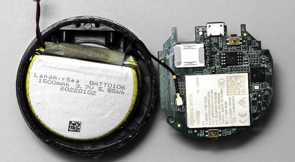
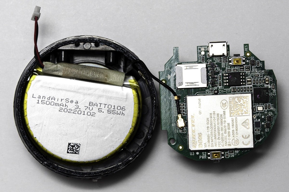
Removing the top fully exposes the top side of the PCB, which has a few notable features.
- A generic-looking GPS antenna or module (like this antenna from Sparkfun). The back of the PCB will reveal more about whether this module contains the GPS chip or not.
- A series of either test points or breakouts for chip GPIO.
- This array of LEDs is visible when the device is active and can be seen through the translucent cover. Closer inspection reveals silkscreened labels for each diode including CHG, CELL, and GPS indicating what aspect of the design the LED is providing status for.
- A power cable (presumably leading to the battery) and on the very right is the USB port, which is soldered on the reverse side of the board. A capacitor and diode are placed directly underneath the battery plug, with what seems to be the diode output pointing straight at a test point and a via.
Another observation can be made about this side of the board – note that there are many unpopulated pads to the left of the GPS unit.
This is frequently done in companies that produce multiple models of similar devices.
Being able to order just one PCB design and simply assemble it differently to produce different models can save costs and time (no need to worry about two different board designs!).
In general, this side of the PCB is pretty simple, which makes sense from an IP and security perspective since the top of the enclosure is see-through.
To learn more about the design we can pull out the PCB and flip it over. This is trivial to do since it isn’t actually screwed or locked in, just a press-fit, revealing a much more interesting underside:
Before diving into the PCB itself, though, we’ll take a look at the components underneath it that were revealed.
Unsurprisingly there is a battery, specifically a 1500mAH lithium-ion one whose power cord is the two-pin one that we saw connected to the plug on the top of the board earlier.
Removing the battery reveals the strong magnet, stuck to its underside with a weak adhesive. Those two items, the battery and the magnet, are the only other two items in the enclosure besides the PCB itself.
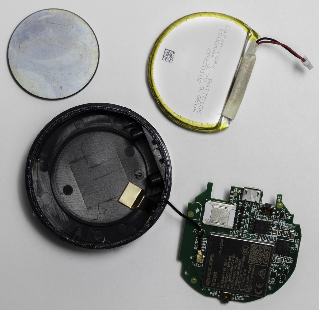
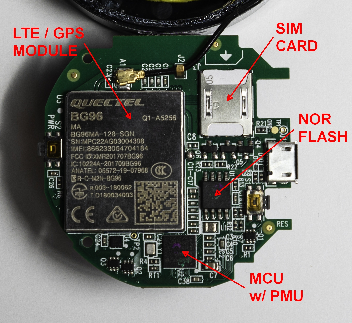
Moving back to the PCB, we can immediately see that this reverse side is much more interesting and informative than the front.
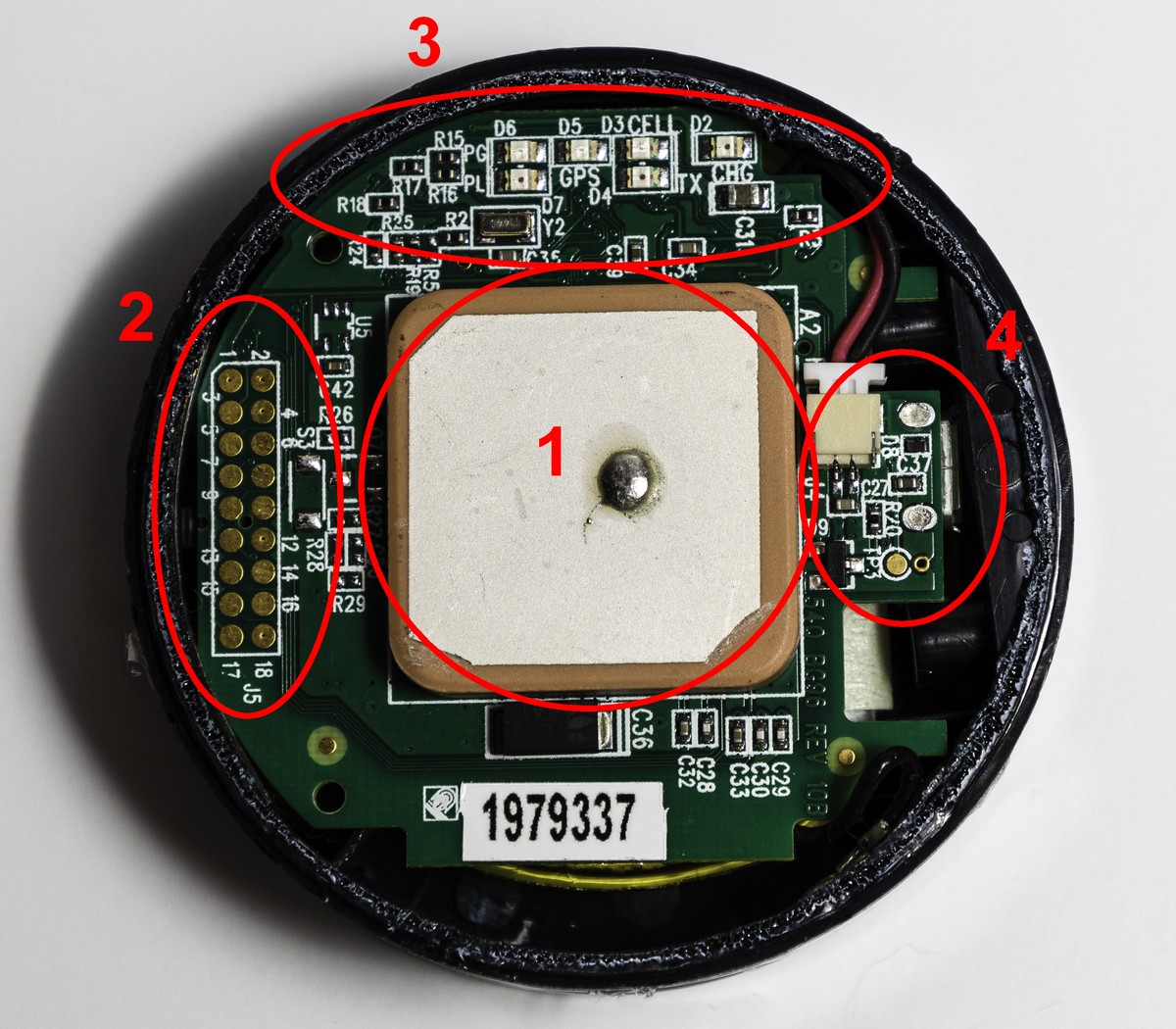
Dominating the design is a large SoM clearly labeled as the BG96 from Quectel, which has a readily available product page online.
Some of the highlights from the module’s product page include its specific advertising for use in asset tracking, its ARM A7 processor, and most interestingly is its optional GNSS (Global Navigation Satellite System) functionality.
According to the product spec sheet it optionally includes GPS, GLONASS, BeiDou/Compass, Galileo, and QZSS.
This answers the question about whether the module on the top of the board was an antenna or a module – if the BG96 has a built-in GPS chip then the item on top of the board must simply be an antenna.
Directly above the BG96 is a clip for the main antenna, labeled A1. This connects to a wire that routes to a solder pad on the inside of the enclosure itself, which indicates that the main LTE antenna has been built into the body of the enclosure.
To the right of the module is the slot for the SIM card, which is naturally required for a device with LTE and cellular capability – the product spec sheet specifies that the BG96 is actually capable of data, voice, and SMS.
The BG96 also supports a wide input voltage range of 3.3-4.3V, which puts the specified nominal battery voltage of 3.7V squarely in the center of the range, which eliminates the need for anything in the way of a buck or boost converter.
There are a couple other large ICs on this side of the board. The first, in an SOIC package to the right of the BG96, is a chip identified as a AT25FF081A, by Adesto technologies.
This chip is simply an 8Mb NOR flash chip with an SPI interface, for any nonvolatile storage required by the system.
The second chip, located on the bottom edge of the BG96 (the side opposite the main antenna), is more interesting: the DA14695, which is a full-fledged SoC microcontroller with RF capabilities in the form of Bluetooth 5.1.
However, the feature that most likely brought it to the forefront of the part selection is its integrated power management unit.
This little chip includes:
- A buck converter
- Four power supply pins for external devices that are active when the chip is asleep
- A hardware battery charger with support for lithium ion batteries
- Brownout detection
So despite the fact that the BLE functionality of this chip is not likely utilized very much, being able to pack a full power management system for battery charging as well as a microcontroller into the same package likely created significant cost savings in the bill of materials.
This chip probably serves as the brains of the unit, and uses its serial interface to send AT commands to the cellular module and its SPI interface for the NOR flash module.
A cryptographic engine and a real-time clock round out security and longevity functionality for this device, providing accurate timekeeping and the possibility for strong cryptographic performance.
There are several good product development practices that were executed by LandAirSea when developing this product that should be highlighted.
Firstly and perhaps most importantly, there are multiple components that were chosen such that multiple functionality was contained in one part.
This is exemplified by choosing to put both the GPS and cellular functionality in one chip (which incidentally also concentrates all major RF concerns to a single SoM which makes certifications easier) as well as choosing an MCU with an integrated power management unit.
These choices not only reduce the overall cost of the BOM, but also greatly simplify the design process by reducing interconnections, board area, and other things that would otherwise have to be considered when creating the PCB design.
Also note that the designers chose NOR flash memory over NAND for its reliability.
In a device like this where space is not at so much of a premium compared to something like a smart watch, making the tradeoff for increased die area is not a huge sacrifice in exchange for that reliability.
Take note of the fact that there are many test points on both sides of this PCB.
It is imperative that being able to get to critical signals without too much precision, and perhaps in an automated fashion like a bed-of-nails test setup, is possible for an electronics product.
Board verification and testing is always critical, even in production-ready products.
One area where perhaps there could have been some cost and size shaved off is in the choice of microcontroller.
While a fairly nice combination, it’s possible that an MCU with just a PMU and less GPIO/peripherals could have been sourced.
It would only need SPI and serial for AT commands and not much else in terms of MCU interconnectivity besides that hardware power management unit.
A chip lacking the extra I/O and the BLE may have been cheaper and smaller.
Also note the fact that a custom LTE antenna, while potentially unavoidable due to the product footprint, will of course add some barriers in terms of acquiring RF certification for your product.
From a high level a GPS module is a relatively simple product, but as this article has shown there is a lot of depth and practical consideration that goes into the components that make a product like this up.
This LandAirSea module makes efficient use of its footprint and its high quantity of reviews with a 4+ star rating indicate its robustness and quality of design.
