
How to Port a Raspberry Pi Project to a Compute Module for Mass Production
Learn all about Raspberry Pi Compute Modules and how you can use them most effectively when developing your own electronic product.

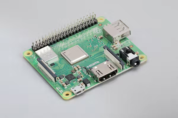
When taking a Raspberry Pi project to a custom PCB, or simply a smaller form factor, many engineers will want to move away from the “classic” single-board computer design to something more minimalistic.
Perhaps your project doesn’t make use of Ethernet or HDMI, and you only need one USB port. These ports on the mainstream Raspberry Pi boards simply add bulk to your design when you don’t need it.
Additionally, 2.54mm headers may not be large on their own but in large numbers their size can add up fast, and if your project doesn’t use most of the GPIO available on the Pi then these extra pins are just in the way.
On the other hand, maybe you need more GPIO than the standard Raspberry Pi boards have to offer, since the Broadcom processor that drives the unit has more GPIO pins than are available on those headers.
If any of the above scenarios aligns with your situation, you will want to consider porting your project to a Raspberry Pi Compute Module.
These are specialized boards that Raspberry Pi offers as complements to their main line of single-board computers.
They mostly have the same internals but with none of the ports or header pins by default, just a compact mating connector designed specifically for the module to be slotted into a larger motherboard.
The idea behind a Compute Module is that it provides the bare minimum hardware required to just run the operating system and store data.
Some Compute Modules may not even do the latter, and require external storage in the form of a micro SD card.
They only have the Broadcom processor onboard (the BCM2837 in the case of the Compute Module 3+ pictured below as well as the Raspberry Pi 3 Model B+), RAM, optional eMMC flash memory, and some other minor supporting hardware.
The CM3+ doesn’t even have its own single-input voltage regulator circuit and requires separate 1.8V, 3.3V, and 5V power supplies to be provided by its host PCB.
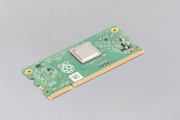
At its core, though, you can be assured that when using the Compute Module, since it uses the exact same processor and has the exact same amount of RAM (1GB) compared to the Raspberry Pi 3B+, the software you write on one will perform very similarly on the other.
Additionally, your program can have access to all the same hardware as the single-board Raspberry Pi.
All of the peripheral drivers for things like the camera ports, USB, etc. are integrated into the Broadcom chip or the module.
So, re-implementing these peripherals on your custom board is not much more difficult than simply providing breakouts from the module’s pins to a port on your board.
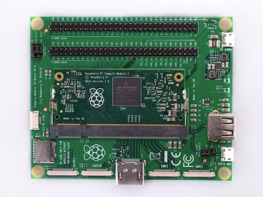
Raspberry Pi provides IO boards like this one that demonstrate how a Compute Module can be made functionally identical to a standard Raspberry Pi with the correct parent board.
Since the Compute Module actually allows for more GPIO than the single-board Raspberry Pi’s, a Compute Module + IO board combination is actually even more flexible.
Looking specifically at the Compute Module 3+ (which will remain in production until January 2026), we see that there are three GPIO banks available on the BCM2837 chip.
The third bank is dedicated to eMMC and internal buses and thus only exposed in a useful manner on the Lite variant where the user must provide their own storage solution.
Bank 0 is what is exposed on the standard Raspberry Pi 3B+ and is composed of GPIO pins 0-27. Bank 1 provides the main useful expansion of GPIO on the Compute Module, offering extra 18 GPIO pins numbering from 28-45.
Bank 0 and Bank 1’s GPIO pins can be separately powered (and thus have separate logic levels) through their own dedicated power inputs, which are provided by the motherboard that the Compute Module is inserted into.
The power supply allows for a range of 1.8-3.3V. In addition to simply providing extra GPIO, Bank 1’s pins can also be used as the I/O pins for a variety of the peripherals that are available on Bank 0, including the SPI, PWM, and I2C interfaces.
This allows these interfaces to run at a different logic level than Bank 0 to perhaps service an external device that requires it.
These extra GPIO don’t come at the expense of the other peripherals. Available through separate dedicated pins on the CM3+ are two camera ports, two serial display ports, USB(OTG), HDMI, and composite.
Note that the use of the cameras can interfere with I2C.
So how do you actually go about using a Raspberry Pi Compute Module, starting with how to flash it?
Using the CM3+ as an example, assuming you didn’t opt for the Lite variant which has no onboard flash memory, the easiest way to flash a Compute Module is using the official IO board.
Below is an image of the I/O board, with a Compute Module 3 mounted into its slot. Note the number of GPIO pins, which far exceeds the number on the single-board Raspberry Pi 3B+.
In the lower right of the board, next to the microUSB port labeled USB Slave, there is a jumper that allows enabling/disabling USB Slave Boot mode.
When this jumper is set in the Enable state, it essentially boots the device in a mode such that when the microUSB port is plugged into a PC, the eMMC flash can be mounted as a storage device like a flash drive.
Note that you may first have to follow the instructions here to initialize the eMMC as a mass storage device so that your PC can recognize it, using the rpiboot utility.
At this point, the disk that mounts to the PC can be treated just like an SD card would be in a normal Raspberry Pi, and you can use your favorite image flashing tool like Balena Etcher or Rufus to flash a version of Raspbian onto.
Now there are a couple other things to consider – neither the Compute Module nor the official I/O board have built-in wireless capability.
If you haven’t implemented it on your custom board, it won’t be possible to conventionally SSH into the device.
The two simplest options are to use a display and connected keyboard to interact with and program the Compute Module, or to use a free USB port to connect an external WiFi dongle to allow SSH access.
More advanced users could also use the serial console to get a shell and program the Pi by hooking it up directly to a PC with a serial-to-USB adapter.
Note that this interface option needs to be enabled using the raspi-config utility before it can be used, similar to SSH.
So despite there not necessarily being the same options right out of the box for interfacing with the Compute Module as a standard Raspberry Pi, there are certainly a lot of options that can be used to make it happen.
Once the hardware has been set up, the eMMC flash has been imaged with a version of Raspberry Pi OS, and a shell has been obtained via one of the methods above, what changes in terms of the software development process compared to a normal Raspberry Pi?
The answer is that it depends on what you are trying to do and how much of the “extra” Compute Module functionality you need and use.
One thing that does need to be considered is that unlike the Raspberry Pi, many peripherals will not be enabled by default since the system configuration can be so much more flexible.
Configuration and enabling of GPIO, peripherals, etc. is done at Raspberry Pi’s recommendation by downloading and editing device tree files, which adds another layer of setup to a project.
The intent of the Compute Module is to provide a very stripped-down Raspberry Pi out of the box, including at the software level.
It is designed expressly for the user to only add what they need to the system, exactly as they need it.
Much of the complexity and added work behind the Compute Module is simply the hardware and its setup process.
Once you have a Compute Module in an I/O board running an operating system, and the peripherals you want to use are initialized and loaded correctly, it can be programmed and utilized in largely the same way as the single-board variants.
For example, GPIO manipulated using a Python library or interfacing with a Raspberry Pi Camera.
All major differences will simply be realized in the setup required to connect the hardware, which is generally well documented by Raspberry Pi in various articles and in their design reference for the I/O board.
It is also likely that users will run into more difficulties as they attempt to use peripherals and GPIO that are not available on the standard Raspberry Pi.
Community-made Python libraries may not support these extra GPIO or properly consider hardware conflicts, so when making use of these peripherals take care to consult the official Raspberry Pi documentation, such as the examples here.
It is also worth noting that many applications of the Compute Module will end up being more deeply embedded and highly customized than projects that only use the standard Raspberry Pi.
In some applications it may not be possible to program the Compute Module from the application motherboard.
Some may program the module using the I/O board and then deploy it, or it may simply be inconvenient to interface with the module for programming while it is in its target board.
Whatever the case, when designing a system around a CM the designers should remain aware of the potential difficulties that can arise when it comes to interfacing with the device.
It’s ideal to build in solutions to these problems, perhaps an onboard WiFi chip or ensuring a programming USB port is included.
Due to the stripped-down nature of the Compute Module there will just have to be considerations made that would not have to be made otherwise when it comes to peripherals that were previously taken for granted.
With all the above considerations, despite the hardware similarities between the Compute Module and the single-board Pi, you should not expect a plug-and-play experience for your existing software, especially given the fact that peripherals should need to be set up.
It is recommended to iteratively bring your Compute Module up to functional equivalence with a standard Raspberry Pi for your application.
For example, if you need a camera then first focus on loading that peripheral driver using the documentation and testing it on its own before attempting to use it with your full application.
Follow this process for any needed peripherals in your system.
Another consideration when prototyping is to simply start with a Compute Module and an I/O board as your prototyping test bed.
If your product will need the extra GPIO anyway, this will be a requirement and it will then be a less jarring transition process.
This also allows swapping out multiple Compute Modules into your prototype I/O board to program or verify them and subsequently deploying them into custom boards with no software changes, making a more seamless jump from prototype to final revision.
If you are early enough in the design process to make this decision and you are fairly sure that a transition to the Compute Module is in the future, this may be a good option for you.
It is clear that the Compute Module series is geared towards more advanced users than hobbyists who may be users of the standard Raspberry Pi.
It is a product expressly meant for industrial applications in contexts where custom hardware is being developed; however that does not mean it requires a computer engineering expert to design with it.
There is a wealth of documentation provided by Raspberry Pi and the community in the form of wikis and PCB design files to help inform the design choices you make in your application
The Compute Module may be exactly what is required to take a product from the lab bench to a real-world application.
