
The Importance of Engineering Documentation and Hardware Revision Control
Revision control and proper engineering documentation are essential to ensure that you only ship quality products to customers.

This article is a guest post by Craig Rettew who is an electrical engineer. He is also one of the experts available to help you inside the Hardware Academy.
Version control is ubiquitous in the software world. There are amazing tools such as GIT and SVN that allow seamless version control for software projects. Both are command line driven but there are also several graphical user interfaces to interact with both systems.
Both systems can be used on any ASCII-based code whether it’s Python, C++, C#, Ruby, or even LOLCODE. They’re great and well tested for text-based projects. This goes for both software and firmware.
Hardware is a bit trickier when it comes to version control. In the hardware world, the tools used to design and develop hardware projects are graphical.
Most development is done in a CAD (Computer-Aided Design) program, such as DipTrace for schematic capture and PCB layout, or Fusion360 for 3D modeling.
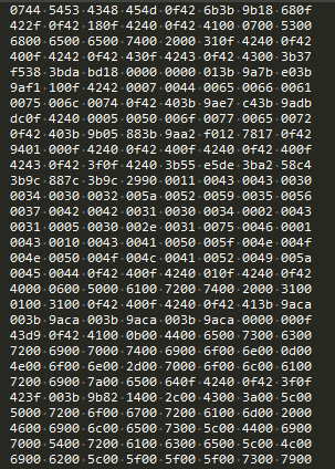
If you open one of these files in a text editor, you would get hexadecimal mumbo jumbo that is not readable by humans.
There are several CAD programs available and I don’t have experience with all of them. I’ve heard murmurs of user’s having some success using the GIT process with the ECAD programs, but it isn’t as seamless and universal as it is with software.
There is an excellent write-up on using KiCad and GIT together which seems like a fairly good version control solution if you’re a KiCad user.
When you boil these programs down, it’s really a fancy way to make and connect different shapes. But how do you know when a shape has been changed, added, or deleted?
There isn’t one blanket approach to version control for these types of programs, but there are some tools and techniques that enable you to put the best process in place.
Commit as often as possible. When I talk about committing, I’m talking about the term used in version control systems which sends a project’s latest changes to a repository. This allows users to see what was changed over time. It’s important to capture changes as often as possible, especially when you’re collaborating with others.
If It’s Not Documented, Did it Even Happen?
When an engineering drawing is created, it usually involves a title block. Title blocks provide all the information needed such as the designer’s name, date, part number, name of part/design, revision, and revision block.
Other than the revision block, the other attributes are self-explanatory. A revision block provides a brief explanation of what changed in a particular revision.
In the engineering world, when a design is finalized, reviewed, and signed-off by everyone involved, it gets “released.” This means that it’s either ready for manufacturing or at least ready to be implemented as the latest and greatest revision. The revision block captures all of these releases.
Adding messages in the revision block with the revision number is similar to a message added during a GIT commit.
There might be previous revisions inside your product that have already been manufactured and released into the wild. The documentation should exist not only for the manufacturer but for your own reference as well.
Like with any company, employees come and go. If the last guy didn’t document what was done, the new guy has to play catch-up and reverse engineer what was previously done.
This is a time and money waster that benefits no one. Establish a documentation process upfront and everyone will benefit from this effort.
Engineering Change Orders
Documentation is imperative when developing a product that is meant to be shared with anyone other than yourself. If you want someone else to know how your widget works, how to operate it, or how it was designed, put it in a document.
When working with larger teams on big projects that involve a lot of different engineers and managers, documentation becomes a full-time job.
Even the smallest of changes can affect the entire product. Let’s say a project’s mechanical engineer decides to use a number 6 fastener instead of a number 4 to affix the circuit board to the housing.
Now, the mounting hole on the PCB needs to change, which means you have to move the resistor that was close to the smaller hole, which leads to more design changes, etc.
This is why Engineering Change Orders (ECOs) are so important. They provide not only documentation of the changes, but also information on how that change effects other parts. All of the people involved on any design that the change touches, sign off on this ECO.
Tools and Techniques
Folder Structure, File Naming Conventions, & Part Numbers
The most universal method for hardware version control is using simple folders and files. It’s best to have a centralized location that you work from. Dropbox and Google Drive are great for this, but if you’re doing top secret CIA alien stuff, you’ll probably need to roll your own centralized server.
Part numbering is also important to differentiate the components with your product. This is good not only for your sanity, but also for when the manufacturer gets the CAD files in order to manufacture your product.
There’s nothing worse than sending over a file called Odor-Sensor-00020-final-for-realz-this-time-v2.zip.
Whatever part numbering scheme you use, all part numbers should be located in a centralized list to avoid duplication and confusion. Spreadsheets work great for this but there are also good tools such as OpenBOM to help manage parts numbers and bill of materials.
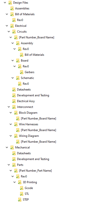
When I’m working on a project I use a particular folder structure to organize all of my CAD files, bill of materials, and documents. I’m wrapped up in the Google ecosystem so I use Google Drive as my central repository.
There are a lot of nuances here and your mileage may vary. But in general, I start with “Rev0” and if there is a major change to a particular design or file, I start a new folder called “Rev1.”
This captures the major changes that will eventually be physically made. A process like this keeps me organized and limits my chances of sending the wrong CAD files to the manufacturer.
In the new Rev1 folder, I will markup or redline a PDF version of the previous revision, making notes of any changes. Then, this redline gets implemented in the new version of the CAD file.
Here is a graphic showing the folder structure I tend to employ.
Built-in Revision Control
Enterprise level CAD programs such as AutoCAD and Solidworks have built-in workflows for revision control, but of course this locks you into their ecosystem.
It seems that other accessible, cloud-based CAD programs are catching up as there are many that include some kind of version control within the program itself.
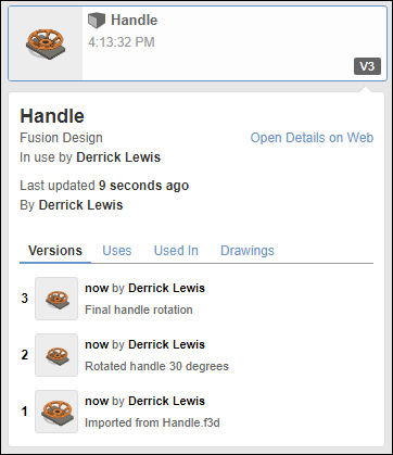
The knowledge AutoCAD has gained from their legacy programs has carried over to the more accessible Fusion360. They have done a fantastic job with its version control.
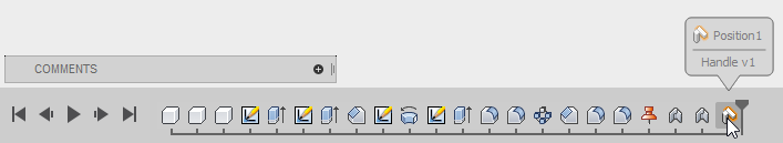
When starting a new design, each change is captured in the timeline. Each time you save your design, a comment box appears so that you can enter what changed, before a new version gets created.
To see any of the changes that were made, you can simply see all the versions or roll back the timeline in each version.
For an enterprise-level solution focused on ECAD, Altium offers Altium365 which is a platform that unites everything needed to design and collaborate on electromechanical projects.
Design teams can collaborate on designs in real-time with comments. The key to its success is the concept of the centralized data management system. No separate versions of projects can live on some remote employee’s laptop somewhere in Montana.
Dedicated Tools
One of the better tools I’ve seen for mechanical design is GrabCAD Workbench. The revision control is pretty amazing and it’s platform is agnostic, meaning it supports all the major CAD formats (for 3D modeling anyway).
There is a powerful visual version comparison tool that will highlight changes to a 3D model showing the difference between the two versions.
All of these features are fantastic for collaboration and for making sure the latest and greatest version of your project is the one handed off to the manufacturer. It creates a very helpful digital paper-trail.
For ECAD, companies have emerged to tackle the hardware version control conundrum. I have yet to try cadlab.io or allspice.io but both look promising. Visual diff, native PCB software files support, and Git client? Count me in.
As with other attempts at hardware version control, these aren’t a blanket solution given that it’s ECAD tool specific. Each is certainly targeting the most popular tools with hopes of including more. My DipTrace fanboy heart will have to wait.
Continuous Integration for Hardware (Rapid Prototyping)
A pure software project allows a developer to do wonderful things in an automated way. Continuous Integration (CI) is a development practice where developers push changes to their shared repository very frequently. Those changes get verified through automated tests and build processes.
The closest thing to continuous integration for hardware is with the combination of 3D modeling and a 3D printer. A mechanical engineer could design something in the morning, have it 3D printed in a couple hours, and physically test their part by the end of the day.
This process is obviously not as quick as software but it’s progress for sure. There are all sorts of 3D printing materials available for a variety of 3D printer platforms. An example of an industry that has been fundamentally changed due to this concept of continuous integration for hardware is the shoe industry.
There have been valiant attempts at “3D printing” electronics such as this drone that flies right off the build platform, but it’s not quite there yet. Electronics don’t just involve a conductive trace, it involves components that are developed in a lab on a microscopic level.
If your PCB is 1 to 2 layers, there are machines that are available to rapidly test the design. I have used a desktop CNC machine for several of my designs in order to test a particular section or an entire design.
It’s not perfect as there is no concept of plated through holes and fine pitched parts can be tricky. Although, it has allowed me to design, fabricate, and test in a single day.
Otherwise, I would have to find out that I got my footprint wrong 2 weeks later when the professionally made PCB shows up (*sad trombone*).
The Ultimate Revision Control System for Hardware
Take a moment with me and dream big. The perfect revision control system for hardware would be as seamless as GIT is for IDEs, such as Visual Studio Code, which is where I do all my software/firmware development.
It would be wonderful to open any CAD tool, install a plugin for GIT, and initialize the directory you’re working from, using your native file types. Each commit would create a PDF of your design (2D or 3D) which could be compared to a previous commit.
The PDF would show what was added, removed, or changed in some kind of obvious way. This would probably involve some kind of image processing and metadata combination.
Each time a design gets released, that commit gets a tag (a label inside GIT) with the revision number, and the releasable documentation gets bundled inside that commit.
For a circuit, the bill of materials could be generated along with the Geber files for the PCB. Throw in an auto-generated ECO while we’re at it.
I believe that the PDF format allows this to be possible since it’s so universal with the added benefit of having a 3D component.
The other beautiful thing about GIT is the portability. If a particular company is using a certain IDE, GIT is still universal, its platform is agnostic.
For hardware, it seems like you’d have to burn down the building in order to start fresh and move to a new tool. The defense industry still uses Mentor Graphics while others have moved to Altium. A portable revision control system is imperative for mass adoption.
Clearly there are a lot of nuances with this idea, but us hardware engineers are jealous of the seamless software tools that are available (cue the tiny sympathy violin).
Conclusion
Processes for revision control are important to put in place. Establish them early in your development, but understand that it may be a fluid process that will evolve over time.
New ideas may emerge and new tools may be invented (see ultimate revision control system above). No matter what process you put in place, it’s all for the common goal of “shipping” quality work. That starts with getting the correct version of your product manufactured and in the hands of your customer.

Thanks Craig for sharing your thoughts on this. Your folder structure was particularly insightful for me!