
Introduction to Battery Chargers
One of the most common types of electronic circuits used in modern portable electronic products are battery chargers. This article will review three common battery chargers ranging from simple to more complex.

First, I review the Microchip MCP73831, which is simple to use and a great battery to start with.
Next, I will review the Texas Instruments BQ24092, which is a slightly more advanced battery charger.
Finally, we will look at a significantly more complex battery charger, the Texas Instruments BQ24703.
I’ll be going down memory lane a bit since the BQ24703 happens to be a battery charger that I designed many years ago when I was a chip designer for Texas Instruments.
The first two chargers (MCP73831 and BQ24092) are both linear chargers, whereas the BQ24703 is a switch-mode buck charger.
If you need to learn the difference between a linear charger and a switch-mode charger be sure to read my previous article on voltage regulators. In that article, I discuss in detail the difference between a linear regulator and a switching regulator, and the same principles apply to battery chargers.
MCP73831
The first battery charger I will review is the Microchip MCP73831. This battery charger is designed to charge a single cell and is made for either lithium-ion or lithium-polymer batteries.

Figure 1 – Schematic diagram for a typical application using the MCP73831.
A single cell lithium battery outputs about 3.6 V. So if you see a lithium battery with a rated output voltage of 7.2 V then it’s made of two cells connected in series. If the battery voltage is 14.4 V then it’s a 4-cell battery pack.
In order to charge multi-cell battery packs you must have either an input supply voltage greater than the battery charging voltage or you need a switch-mode boost charger that can produce a charge voltage higher than the input supply.
The Three Stages of Charging a Lithium Battery
There are three stages of charging a lithium battery: the pre-charge stage, the fast-charge stage, and the charge termination stage.
When in pre-charge or fast-charge the charger regulates the amount of current going into the battery. But during charge termination the charger is regulating the voltage going to the battery while measuring the current flowing into the battery.
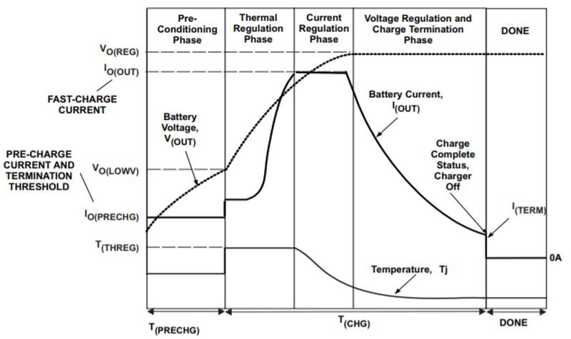
Figure 2 – Charging stages for rechargeable lithium batteries (graph is from the Texas Instruments BQ24092 datasheet)
1 – Pre-charge stage
The first stage is the pre-charge stage, also known as the trickle stage. During this stage, the battery charger sends only a small amount of current (trickle charge) into the battery. If a battery is detected, the charger will then begin the charging process.
The trickle charge is a small percentage of the full charge current. The goal of this stage is to charge the battery up to a certain point so that it can be fast-charged in the subsequent phase (see below).
The charger automatically goes into the pre-charge stage when a battery is highly discharged and with a voltage below a certain threshold.
Once the pre-charge has started, the battery voltage is monitored by the charger until the pre-charge voltage threshold is reached.
The pre-charge voltage threshold is a predefined percentage of the maximum charge current that you are responsible for programming.
Once the battery voltage exceeds the pre-charge voltage threshold, the battery charger enters the fast-charge stage.
2 – Fast-charge stage
The fast-charge stage, also known as the constant current stage, regulates the amount of current going into the battery.
Both the pre-charge and fast-charge currents are set by a single resistor on the PROG pin of the MCP73831.
The constant current is used to charge the battery, which is regulated based on the maximum charge current you have selected.
For the MCP73831, the maximum charge current is set by tying a resistor from the program pin to ground (see Figure 1). You can select a charge current from 15 mA all the way up to 500 mA.
Once the battery is close to being charged during this fast-charge stage, it then switches to the charge termination stage.
3 – Charge termination stage
The final stage of charging is known as the charge termination stage or constant voltage stage. During this stage, the battery charger switches into a voltage-controlled mode, where it regulates the voltage going to the battery instead of the current.
Although the voltage to the battery is what is being regulated, the charger monitors the charging process by measuring the charge current.
Once the charge current while in voltage-controlled mode drops below a predefined percentage of the programmed current, the charger knows that the battery is fully charged, and the charging process is terminated.
After the charge cycle is complete, the battery charger will continue to monitor the battery voltage. If the battery voltage drops below a pre-set recharge threshold, the charger will initiate a new charge cycle and the whole process repeats.
You will notice on the graph in Figure 2 that there is also a fourth stage called thermal regulation. However, this stage only comes into play if the power dissipation is high enough that the charger’s internal temperature exceeds 125C.
If the system is designed so the charger never reaches this temperature then the thermal regulation stage is not entered. I discuss this in more detail under the power dissipation section below.
Setting the Fast-Charge Current
The fast-charge current for the MCP73831 is set by a resistor placed on the program pin (PROG) to ground. The fast-charge current is calculated by the following equation:
Charge Current = 1,000 / Resistance (Equation 1)
For example, if the resistor is a 2,000 ohm resistor, then the fast-charge current would be calculated as:
Charge Current = 1,000 / 2,000 = 0.5 A = 500 mA (Equation 2)
Note that 500mA is the maximum charge current for this charger. If a 4,000 ohm resister were used instead, the maximum charge current would only be 250 mA.
The exact fast-charge current setting will depend on the capacity of the battery and the maximum current that can be supplied by the external voltage source.
When charging a lithium battery, the maximum charge rate should be typically 1 C, which means that:
Charge Current = 1 x Battery Capacity (Equation 3)
For example, if you have a 500 mAh battery, then a 1 C charge rate is 500 mA. If you have a 150 mAh battery, then a 1 C charge rate would be 150 mA.
The absolute maximum charge current for a lithium battery is typically 2 C. Therefore, if you have a 150 mAh battery, then the absolute maximum charge current would be 300 mAh.
While it’s possible for some batteries to go this high, you generally want to stick to a 1 C rate unless the battery specifies that it can be charged at a higher charge rate.
You also need to take into consideration the maximum current that can be supplied by your external power supply. You need to design the system so that the input current never exceeds the maximum current rating for the external supply.
For a linear charger the input current coming from the external supply is essentially equal to the fast-charge current setting.
However, for switching regulators the input supply current will be considerably different from the fast-charge current going to the battery.
For a buck charger the input current will be less than the battery current, but for a boost charger it will be higher than the battery current.
Power Dissipation
It’s important to keep power dissipation in mind when working with battery chargers, especially linear ones like the MCP73831. Linear chargers are not very efficient under certain circumstances and it’s crucial that the charger does not overheat. Otherwise, the charging current will be automatically reduced below the desired level in order to keep the temperature from exceeding the maximum.
Power dissipation in a linear charger (or linear regulator) is determined based on the:
- Amount of load current
- Voltage differential from input to output
The higher the load current or voltage differential, the higher the power (Remember: Power = Voltage x Current).
The maximum power dissipation and the likelihood of overheating typically occur when transitioning from the pre-charge phase to the fast-charge phase.
At this point, the battery voltage is at its lowest point so the voltage difference across the charger is maximized, and the current is also at maximum when in fast-charge mode. This is the point at which the voltage differential and load current are both at their maximum.
The MCP738 is available with different battery voltage threshold set points when transitioning from pre-charge to fast-charge. As an example, let’s assume this threshold is 70%. This means that when the battery voltage reaches 70% of the regulated output voltage the charger will switch to fast-charge mode.
For a 3.6 V lithium battery, the regulated charge voltage when in constant voltage mode is 4.2 V. 70% of that is roughly 3 V, therefore the battery will be at 3 V when transitioning from pre-charge to fast-charge.
Note that the MCP73831 is available with 4 different regulated charge voltages: 4.2 V, 4.35 V, 4.4 V, and 4.5 V.
Let’s assume we’re charging from a USB port, which supplies a voltage of 5 V. Therefore, there is 5 V on the input and 3 V on the output at the beginning of the fast-charge phase. That equates to a 2 V differential.
If the fast-charge current is set to 500mA, then the charger will dissipate 1 W of power at this transition.
You can consult the datasheet for the charger to determine the Theta-JA rating. This is typically listed under “thermal characteristics” or “temperature specifications”. Theta-JA will be reported in C/watt.
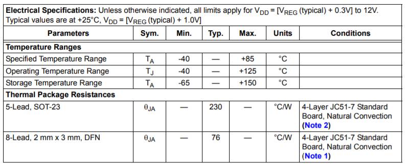
Figure 3 – Thermal specifications from the MCP73831 datasheet.
To determine how much your charger will heat up, use the equation:
Temperature gain = Watts Dissipated x Theta-JA (Equation 4)
This equation tells you how much the component will heat up above the ambient air temperature. To get the absolute temperature you must still add the ambient air temperature to equation 4.
For example, if you calculate the temperature gain to be 50 C, and the ambient air temperature is 40 C, then the component will be at 90 C.
Most electronic components are specified up to 125 C. Always avoid exceeding this temperature otherwise the charger will reduce the charge current as necessary to keep the temperature below 125C.
Package type: SOT 23 versus DFN
The MCP738 is available in two packages, including a leaded SOT-23 package and a leadless DFN package. The DFN has significantly better thermal characteristics than the SOT-23.

Figure 4 – The two available packages for the MCP73831.
SOT-23: The SOT-23 has a Theta-JA rating of 230 C/watt. So if the charger is dissipating one watt of power, it will heat up by 230 C. If you assume you’re at room temperature (25 C) the charger is actually going to heat up to 255 C.
This will definitely trigger the thermal regulation stage which will reduce the charge current to ensure the charger temperature stays under 125C. The SOT-23 package should only be chosen for lower power applications.
DFN. The DFN package, on the other hand, has a Theta-JA of only 76 C. Therefore, for every 1 watt of power the product will only heat up by 76 C. Again, assuming you’re at room temperature, the product is going to heat up to 101 C. This is below the 125 C threshold and much better than the SOT-23.
So for applications with high power dissipation requirements the DFN package is the best choice.
The key criteria for selecting a linear charger to meet the required power requirements includes the package (which accounts for the Theta-JA specification), the power being dissipated, and the maximum ambient temperature that the product is going to operate in.
With switching chargers, overheating becomes less of an issue because they tend to be a lot more energy efficient and they don’t typically dissipate a lot of power.
Protecting your Battery
As you may or may not know, lithium batteries can be very volatile. If you overcharge them or they get shorted, they can catch on fire or explode.
You’ve all likely heard of the Samsung Galaxy phones that kept catching on fire. Protection is very important to consider when working with these batteries for this reason.
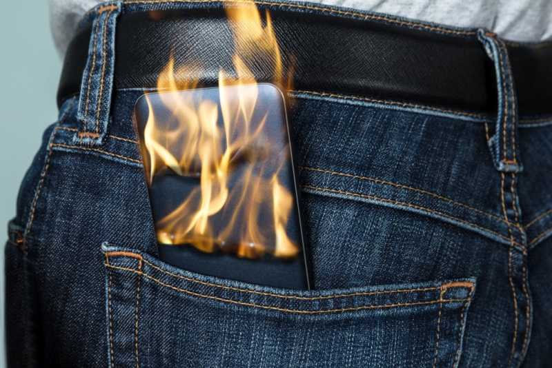
Figure 5 – Without proper protections a rechargeable lithium battery may catch fire or explode.
There are two options you can take when it comes to protection:
Option #1: Choose a battery with built-in protection. I almost always recommend that you go with a battery that has protection built in, at least initially.
If you look at a lithium-polymer battery, for instance, many of them will have a tiny circuit board under some tape (usually gold colored) that’s located at the top where the leads come out.
That circuit board is already built in and it’s what protects the battery. It prevents it from overcharging or being short circuited.
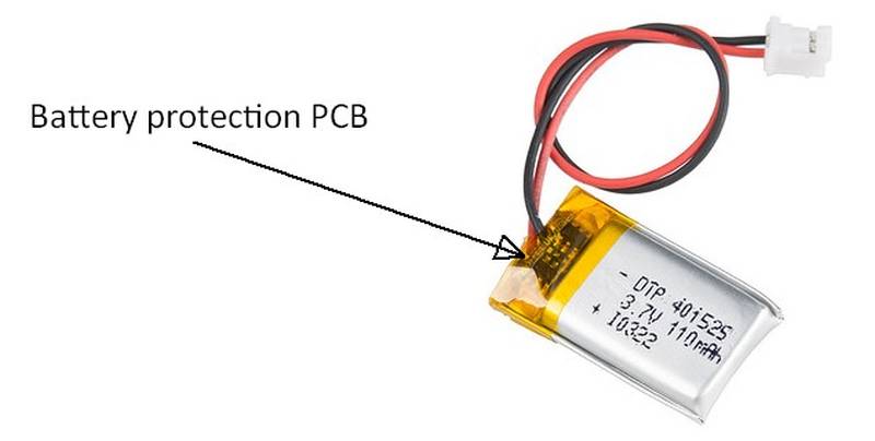
Figure 6 – I recommend that initially you stick with lithium batteries that have the necessary protection PCB already built-in.
Option #2: Design the protection yourself. You could design the protection discretely as part of your own product or on your own board. However, I don’t typically recommend this in the beginning.
If your circuit is not working correctly, you risk the battery exploding while you’re trying to get the circuit to work.
I almost always recommend sticking with batteries that have this protection built in. That way you simply don’t have to worry about it.
Summary of the MCP73831:
- Limited to a maximum charge current of 500 mA
- Single cell charger only
- Linear charger (versus a switch-mode charger)
- Only five pins total
- Single status output pin
- Single pin for setting the various charging currents
- No ability to monitor the battery temperature
Texas Instruments BQ24092
Similar to the MCP73831, the BQ24092 is a linear battery charger for charging a single lithium cell. The MCP73831 only has 5 active pins, whereas the BQ24092 has 9 active pins.
One of the extra pins allows you to independently program the pre-charge and charge termination currents separately from the fast charge current.
Another additional pin provides a status output indicating there is a sufficient input supply voltage present. Another pin monitors the battery temperature, and finally a fourth additional pin is a charge current override function for USB applications.
We’ll look at all of these extra pins more in-depth shortly.
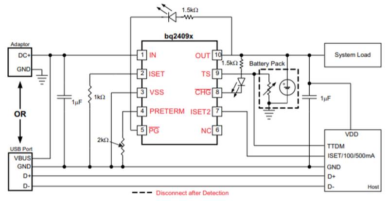
Figure 7 – Typical application diagram for the Texas Instruments BQ24092 battery charger.
Higher fast-charge current
One of the big differences between the BQ24092 and the MCP73831 is the maximum charge current. With the MCP73831 you can program the fast charge current to be from 15 mA to 500 mA.
With the BQ24092 you can program the charge current between 10 mA and 1,000 mA. The charge current is set via resistor tied to the ISET pin.
Because the BQ24092 has a higher maximum charge current, it’s especially advantageous to use when charging larger batteries.
As discussed before, you typically want to charge a lithium battery at a 1 C rate.
For example, if you have a 500 mAh battery, you want to charge it with a maximum charge current of 500 mA. If you have a 1000 mAh battery, on the other hand, then you want to charge it at a maximum current of 1000 mA.
If you use a charge current lower than 1C the charging process will take an unnecessarily long time. Since we all want devices that charge as fast as possible you will usually want to charge at the maximum rate allowed by the battery.
There wouldn’t be a huge benefit to using the BQ24092 over the MCP73831 if you’re using a 500 mAh battery. However, if you have a battery that’s 1,000mAh, then the BQ24092 would allow you to charge it twice as fast as the Microchip battery charger.
Pre-charge and charge termination currents
To quickly review, there are three different charge current levels that you typically need to program for a battery charger:
- Pre-charge current. This is also known as the preconditioning charge current or trickle charge current. It is a low current that pre-charges a battery if it is highly discharged. You can’t (or shouldn’t) immediately begin fast charging a depleted lithium battery. Think of this preconditioning stage as similar to warming up your car’s engine before driving it on a cold winter day.
- Fast-charge current. Once the battery gets up to a certain charge level, typically about 10% of full charge, then the charge will transition into fast charge mode. This is when the charge current is at the maximum.
- Termination current. The charger outputs a regulated voltage and monitors the charge current going into the battery. Once the charge current goes below a certain threshold, called the termination threshold, the battery is considered fully charged, and the charging process stops.
The MCP73831 uses a single resistor to set the pre-charge current, the fast-charge current, and the charge termination current.
This can be somewhat limiting, so the BQ24092 provides two separate pins for programming the charge currents. One pin sets the fast-charge current and the other pin sets the pre-charge and charge termination currents.
Charge current override function for USB
The BQ24092 also has a special input pin called ISET2 that allows you to override the programmed charge current for USB based charging applications.
When the ISET2 pin is high, the charge current is set to 500 mA. When this pin is left floating, the charge current drops to only 100 mA. When the ISET2 pin is pulled low, the programmed charge current is used.
A USB port on a computer (in USB lingo this is called a Standard Downstream Port or SDP) can, at most, supply 500 mA of current.
In the original USB specification a device had to request permission from the host (via a process called enumeration) in order to draw that 500 mA. Without enumeration the maximum allowable current was only 100 mA.
A lot of devices (especially with dead batteries) didn’t find 100 mA to be enough to even power up to initiate the enumeration process. So the USB spec was updated in 2013 to allow up to 500 mA without enumeration.
The BQ24092 was released prior to that USB spec update so that is why it offers a 100 mA setting for USB functionality even though that current level is no longer used for USB.
Power Good Pin
Both the MCP73831 and BQ24092 have a pin that illuminates an LED to indicate when a charge is in progress. This same pin can also be used as an output pin feeding to a microcontroller allowing the microcontroller to monitor the charging process.
On the MCP73831 charger, this pin is called the STAT pin while on the BQ24092 it’s called the CHG pin.
However, unlike the MCP73831, the BQ24092 also has a Power Good pin (PG). This pin indicates (via an LED or I/O pin to a microcontroller) that the power source feeding the charger is above a specified acceptable voltage threshold.
The PG function is beneficial because a lot of components will misbehave if they don’t have the appropriate input voltage supply.
Battery temperature sense
Another additional important advantage of the BQ24092 compared to the MCP73831 is that it includes a temperature sense pin. This allows the charger to monitor the battery temperature, and to adjust the charging current as necessary to prevent the battery from getting too hot.
There are four battery temperature thresholds: 60°C, 45°C, 10°C, and 0°C. Normal charging occurs between 10°C and 45°C.
If the battery temperature is between 0°C and 10°C then the fast-charge current is reduced by half. If the temperature is between 45°C and 60°C the maximum regulation voltage is reduced to 4.1 V. If the battery temperature is above 60°C or below 0°C then the charger is disabled.
Texas Instruments BQ24703
I’m especially excited to review the BQ4703 battery charger because this happens to be a charger that I designed for Texas Instruments when I was a design engineer there years ago.
This battery charger is considerably more complicated than the first two we’ve looked at, but this article will go through it one step at a time.
We will start by considering a few of the primary things that differentiate this charger from the previous two chargers. Then, we’ll review the typical application schematic diagram.
Switching Regulator
The BQ24703 has many added features when compared to the relatively less complex MCP73831 and BQ24092. However, the first thing that sets this charger apart is that it’s a switching charger.
As I’ve mentioned, linear chargers (like the MCP73831 and BQ24092) waste a lot of power, especially if the input voltage is much higher than the output voltage.
This wasted power is dissipated as heat. If the temperature is too high, the charger is forced to reduce the charge current to prevent the overheating of the charger. When this happens the battery will take longer to charge.
Just as with a linear regulator, a linear charger wastes more power when the input voltage is significantly higher than the output voltage.
Side Note: A linear charger is really just a linear regulator with the ability to regulate voltage or current (depending on the charging stage), so many of the same fundamental concepts apply to both. The same is also true for switch-mode regulators and switch-mode chargers.
There are two types of switching chargers, a buck and a boost (just like switching regulators).
For more details on linear and switching regulators see my previous blog on how to pick the right voltage regulators for your project.
A buck regulator takes a higher voltage and steps it down to a lower voltage, while a boost regulator takes a lower voltage and steps it up to a higher voltage.
The BQ24703 is a buck switch-mode charger. Therefore, the input voltage needs to be higher than the voltage of the battery it’s trying to charge. This type of charger is especially beneficial compared to linear chargers when you have a large voltage differential between your input voltage and output voltage.
For example, let’s say your input supply is 12 V but your battery is only a 3.7 V lithium. A buck-switching charger like the BQ24703 is going to waste a lot less power than a linear charger in this application.
It will also charge the battery faster because it will be able to stay in fast charge mode and use the specified maximum current to charge the battery since it won’t enter thermal regulation mode.
On the other hand, if the input voltage is only 5V (such as with USB chargers) then a linear charger probably makes more sense. Linear chargers are less complex, require fewer components, and are cheaper so only use switch-mode chargers when really necessary.
Multi-cell charger
Multi-cell chargers allow you to stack up multiple cells in series to obtain higher output voltages.
For example, instead of just a single 3.7 V cell, a multi-cell charger would allow you to stack up two, 3.7 V cells to create a 7.4 V double-cell battery. You could even stack three cells to get 11.1 V, and so on.
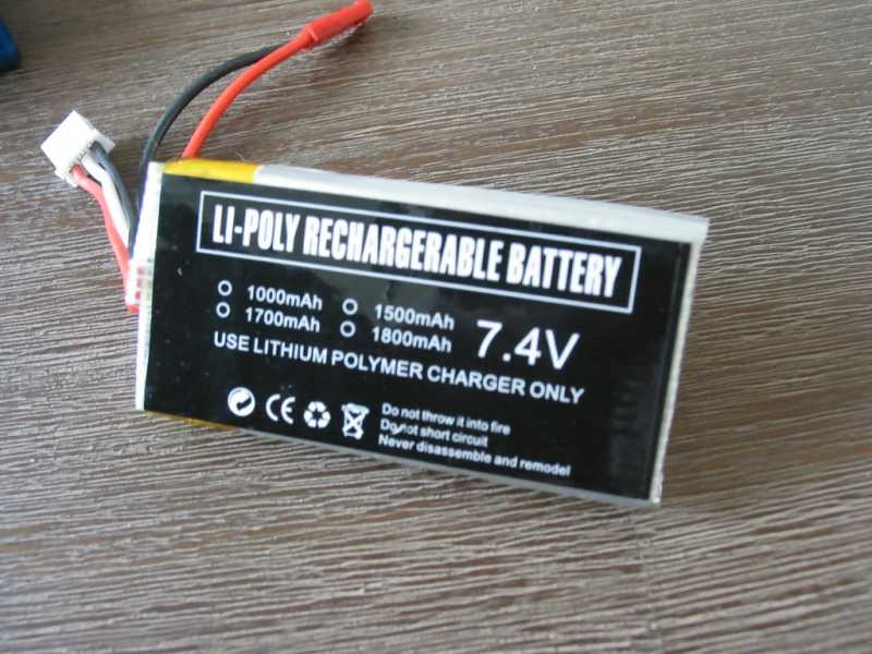
Figure 8 – Two-cell lithium polymer battery pack with a 7.4 V output voltage.
When charging multiple cells with a linear charger or buck-switching charger, the input voltage must be higher than the voltage of the battery you’re trying to charge.
The way around this limitation is to use a boost switching charger, which can take a small input voltage and step it up to a higher output voltage. For instance, this means with a boost charger you can charge a 2-cell stack (Vbat = 7.2 V) from a 5V power supply.
Dynamic power management
Another key feature of the BQ24703 is called Dynamic Power Management (DPM). This means that the charger can dynamically change the battery charge current based on the amount of available current.
For example, say the maximum current your AC adapter can supply is 1 A and your system is pulling 400 mA while you are also trying to recharge the battery. The BQ24703 will then automatically set the battery charge current to 600 mA.
IBAT = IADPT – ISYS
IBAT = Battery charge current, IADPT = Wall adapter current, and ISYS = System current.
In this same example, if the current required by the rest of the system suddenly decreased to only 200 mA, then the DPM feature would allocate up to 800 mA for charging the battery. Of course, this would only occur if the fast-charge was set for 800 mA or higher.
DPM allows the battery to always be charging with the maximum available current. The less current the system uses, the more current the charger allocates to recharge the battery.
System selector switch
In addition to Dynamic Power Management, the BQ24703 also integrates a system selector switch.
This allows you to, manually or automatically, switch the system from being powered from the AC adapter or from the battery.
For example, when powering your product from an AC adapter, if you suddenly unplug it, then the BQ24703 will automatically switch the system to be powered from the battery.
Then, if you plug it back into an AC outlet you can also have it setup to switch back to AC power.
This function is implemented via two external MOSFET switches which are controlled by the BQ24703.
Schematic review
Next, we’re going to look through the typical application schematic from the datasheet for the BQ24703 to delve into this charger further.
Refer to the typical application diagram on page 10 of the datasheet which is also shown below in Figure 9.
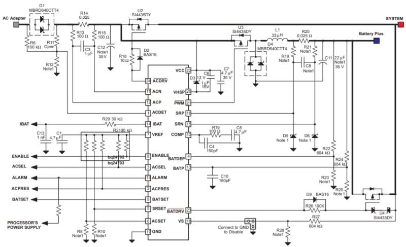
Figure 9 – Typical application diagram for the Texas Instruments BQ24703 battery charger.
MOSFETS: There are several different MOSFETs, including U1, U2, and U3. All of these are P-MOSFETs. Note that U1 is not labeled in the diagram but is located in the bottom right corner of the above schematic.
U1 and U2 perform the system selector function. When U1 is turned on the system is powered from the battery, and when U2 is turned on the system is powered directly from the AC adapter.
U1 is driven by the BATDRV pin and U2 is driven by the ACDRV pin on the BQ24703.
These switches are called break-before-make which means one switch is turned off before the other switch is turned on. This ensures that both switches are never turned on at the same time which would short the AC adapter voltage directly to the battery.
Buck switching regulator: The MOSFET labeled U3 combined with diode D4 and inductor L1 form the core circuit for the buck switch-mode charger. The gate of U3 is controlled by the BQ24703 via the PWM pin.
AC adapter current (ACP/ACN): Coming off the AC adapter input is resistor R14, which is a sense resistor. The BQ24703 measures the voltage drop across this resistor to determine the AC adapter current. R13, R15, and C3 all form a low-pass filter so any switching noise is removed from the adapter current sense voltage.
This all allows the charger to measure the current being pulled from the AC adapter. This is important so that the charger knows how to dynamically manage the power (DPM), and how much current is available to charge the battery.
ACDET pin: There’s also an AC detect pin that serves as an AC adapter detect. This is just one pin that ties to the AC adapter voltage through a resistor divider. It allows the charger to know if the AC adapter is present.
If you’re powering the system directly from the AC adaptor and you suddenly unplug it, the charger will detect that it’s been unplugged and will automatically switch to power the system from the battery.
IBAT pin: The IBAT pin outputs a voltage that’s proportional to the battery charge current. You could feed this into an Analog to Digital Converter (ADC) in your microcontroller to monitor the current charging the battery.
VREF pin. The VREF pin outputs a regulated 5 V that can be used as an accurate reference voltage for any of the resistor divider set points or for pull-up resistors on any of the open-drain outputs.
ACSEL: The AC select pin allows you to manually select whether the AC adapter or the battery powers the system.
ALARM: An alarm condition is generated if the battery is detected as being depleted.
ACPRES: The AC present pin is an output that tells you if the AC adapter is present or not.
SRSET and ACSET: These are two voltages that you set up through a resistor divider that set the adapter current and battery charge current.
VS: This pin monitors the system voltage in order to implement the break-before-make function that I mentioned for the system selector function.
BATP: This pin monitors the output voltage on the battery via a resistor divider. This forms the feedback loop which regulates the output voltage of the charger.
BATDEP: This pin ties to another resistor divider off the battery voltage. It is for setting up the alarm if the battery voltage falls below a certain voltage (which is set by the ratio of the resistors in the divider).
COMP: Any circuit that has a feedback loop has the potential to become an oscillator if that feedback goes positive. The RC network connected to this pin helps to compensate for this feedback loop to prevent undesired oscillations.
SRP/SRN: These two pins connect across a sense resistor for measuring the battery charge current. Just as with the AC adapter sense resistor, there is a low-pass filter (R19, R21, and C8) to filter out any switching noise.
VHSP: This is an internal voltage supply pin that generates a voltage that is a fixed number of volts below the AC adapter voltage. This voltage then is used to drive the P-FETS with a fixed gate voltage.
If the AC adapter voltage is above 10.5 V then VHSP will equal the adapter voltage minus 10 V. For example, if the adapter voltage is 12 V, then VHSP will be 2 V. This is done to ensure that the FETs don’t receive a gate drive voltage higher than they can tolerate.
Conclusion
In this series we’ve closely reviewed three different battery charger solutions that work well in new electronic products.
We started with the relatively simple MCP73831 from Microchip. This is a single-cell linear charger with a maximum charge current of 500 mA. It can be a good solution for many USB based charging applications.
When selecting a linear charger, don’t forget to pay close attention to the package type, power, and the maximum ambient temperature that your product is going to operate under. Nothing will kill your startup faster than burning a customer, so be certain to have battery protection to avoid overcharging or shorting the battery.
Next, we reviewed the slightly more advanced BQ24092 from Texas Instruments. Like the MCP73831 this is also a single-cell linear battery charger, but it has a maximum charging current up to 1A.
It offers more control over the pre-charge and fast-charge currents, and has various termination states that you can program independently. It also includes a temperature sense pin for monitoring the battery temperature.
Finally, we reviewed one of my designs in the BQ24703. This is a switch-mode buck charger with the ability to charge multiple cells. It also includes advanced features such as Dynamic Power Management and a system selector.

Hi john, thank you for posting those amazing informations. I am trying to use MCP73831 to charge a 4.2v Lipo battery. Does this chip has overcharge protection function? Do i need to add an extra overcharge protection circuit?
Hi john,thanks for this post about battery chargers.
How Charger and Cell Balancer work in BMS? I have three cell LiPo battery. I want to make BackUp system with battery. I will use BQ77904 protection ICs and Max1757 Charger Ics. Have you any suggest?
thanks for this detailed post about battery chargers
Hello John,
Thanks for the article.I want to use MCP73831 to charge 10440 li-ion battery in my circuit ,does it need any protection circuit?
because there is no protection circuit on LI-ion batterys , and they are less volatile than Li-Po batteries.
Yes, absolutely you need protection for lithium ion batteries. Don’t even think of not having the necessary protection.
I can not found any 10440 Li-ion battery with protection circuit,is there any 10440 Li-ion battery with protection circuit on it?
or i should design this protection circuit in my design?
Hey John,
Another great article! The technical difficulty was pushing the level if my understanding but I do enjoy learning new things.
As always, best to you!
Emerson
Thank you Emerson! That is fantastic that you are pushing yourself to learn as much as possible. You have the right mentality.