
Migrating from Arduino to STM32 Microcontrollers
Arduino is a fantastic platform for learning electronics and building proof-of-concept prototypes, but it’s not typically feasible for commercial products. Discover what it takes to migrate from Arduino to an STM32 microcontroller.

The Arduino platform has enabled an incredibly low barrier of entry for hobbyists and startups to develop their own embedded devices.
The wide array of development boards available, the simple programming and uploading interface, and the expansive community make it an attractive first choice for product developers.
However, as the needs of a project grow and change over time, the Arduino platform can begin to feel constraining.
A primary cause of this is the relatively limited array of hardware choices, caused by the considerable amount of behind-the-scenes work required to take a commercial microcontroller and fully integrate it into the Arduino software.
The majority of Arduino microcontrollers are 8-bit AVR chips (referring to the internal data bus widths and the instruction set architecture), and these types of processors are limited in terms of CPU performance.
The performance hits are compounded by the fact that in hiding much of the low-level configuration from the user, software running on an Arduino is practically guaranteed to not be fully optimized. Portability and simplicity, first and foremost, are emphasized by the platform.
For these reasons and others, when it comes time to scale up the performance and overall flexibility of your embedded device, it generally becomes time to move away from Arduino.
What is used in a massive percentage of embedded systems in industry are 32-bit ARM chips, powering devices like modern automobile computers and many others.
These chips are unmatched when it comes to price vs. performance, and ARM processors are a long-time staple of embedded computing that show no signs of falling off.
An especially popular option that retains a lot of the selling points of the Arduino platform is the STM32 series of microcontrollers.
With CPU clock speeds going as high as 550MHz and having an enormous variety of chips to choose from, they open up a whole new world of possibilities.
Migration – Software
You may have heard of projects like STM32duino, which aim to make some popular STM32 development boards compatible with the Arduino platform.
While this may be an attractive middle ground for some, it is outside the scope of this article, and can still suffer from the optimization issues I just mentioned.
The most significant shift from Arduino to STM32 is by far the programming experience.
Generally, an Arduino project will consist of a single code file, the ‘sketch’, with supporting libraries, third-party or otherwise, being incorporated in larger projects using Arduino’s library import tool and writing “#import <library.h>” at the top of the sketch file.
Additionally, the code comes pre-structured with setup and loop functions, with the contents of the setup function being run once on startup, and the loop function running again and again indefinitely when the setup function has finished executing.
Even with the inclusion of third-party libraries, the majority of user-provided code will still end up in this single sketch file, with the user writing definitions for these setup and loop functions as well as potentially other helper functions.
These qualities are specific to the Arduino platform, which is why Arduino sketches also have a proprietary .ino file extension.
The actual language used by the Arduino platform, however, is C++, a general-purpose language whose true project structure and supporting programs have largely been hidden by the Arduino IDE.
Both C++ and its older sister language, C, use two file types as part of the codebase a user will write and/or interact with programmatically: source files, defined by the .cpp or .c file extension, and header files, defined by the .h file extension.
An .ino file functionally is the same as a single .c file. Variables are defined there, as well as functions.
A header file will instead provide things like function declarations for external libraries, or more generally, declarations for some interface that is also defined by a corresponding source file.
What this enables, for example, is that a library to multiply matrices may exist, with the actual logic for doing so defined in a file called “matrix.c”.
If several files wish to make use of those functions, it is wasteful and actually forbidden to effectively redefine these functions over and over again by including “matrix.c” repeatedly.
Instead, a second file, “matrix.h”, is created that contains declarations for those functions, which are effectively just pointers to a function that has been defined in only one place.
Now, we can instead just include “matrix.h” in every file that needs to use the matrix library, which does not wastefully repeat full definitions of functions.
If these ideas are unfamiliar to you, you should seek out introductory lessons about C/C++ programming, because these concepts are foundational in this transition.
A typical C/C++ project will have a source file called main.c that, much like the .ino file for Arduino, contains the entry point to the application, a function called main.
The key difference is that unlike a sketch file, the main function is the only ‘default’ function that is run automatically on startup, as opposed to the pair of functions “setup” and “loop” mentioned above.
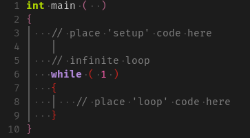
This is a trivial difference, however structuring your main function as follows will set up a program to execute in the same way an Arduino sketch does:
Generally there will also be a variety of other source and header files making up the project, some which will be created by the programmer and some that will be provided by the IDE.
This actually brings us to the next major element of the programming experience. What software is being used to create and upload code, if not the Arduino IDE?
This is actually a very open-ended question, as even Arduino-compatible chips may be used outside of the Arduino environment.
Microcontrollers may be programmed in a “bare-metal” environment, which means that a programmer uses separate, typically customized tools to edit code, then compile it into an executable program, and upload it to the chip.
Programming like this is the best way for a more experienced developer to truly maximize performance, but it is an especially large leap coming from Arduino, which combines the editing, compiling, and flashing sequence seamlessly and does all the heavy lifting under the hood.
The middle ground is to use an IDE that still provides automated compilation and uploading to provide an integrated experience, but allows pulling back the cover over the actual code being written and still allows customization of the compile/upload process. ST, the company who manufactures the STM32 microcontrollers, provides an excellent example of this in the form of their custom IDE, STM32CubeIDE.
STM32CubeIDE is much larger, and has more features, than the Arduino IDE. It is an Eclipse-based IDE, which means that it is a modified version of the ubiquitous general-purpose Eclipse code editor.
This means that code will have features like auto completion, and the ability to search for definitions or declarations of variables and functions, which makes the actual process of programming for larger applications much easier.
Perhaps its most powerful feature, however, is its integration with STM32 firmware generation software, which provides a graphical interface for enabling and configuring the various hardware components within an STM32 and automatically generating firmware and setup functions that match the selected options.
The following image is a screengrab of the pinout tool, which is available for practically every available STM32 microcontroller. In the below image, an STM32F401CCFx chip is being used, and its I2C1 interface (out of 3 available) is being set up.
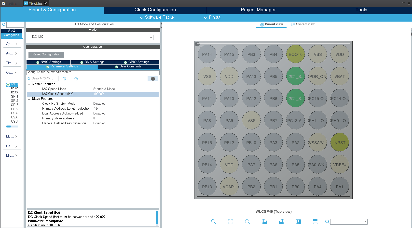
You can see that the I2C1 bus has been enabled, and two pins in the image to the right have been highlighted green and labeled to indicate which I2C pins they are. The window to the left shows the various configuration options that are available to that I2C bus, such as the ability to change its speed.
All options selected in this GUI may be pushed as auto generated code to the project by saving the configuration and selecting the “Generate Code” option in the upper toolbar.
This feature makes taking full advantage of the powerful peripherals available to the STM32 chips incredibly straightforward, and makes it much less necessary to spend time poring over a datasheet figuring out how to increase the resolution of your analog-to-digital converter or set your SPI bus to slave mode.
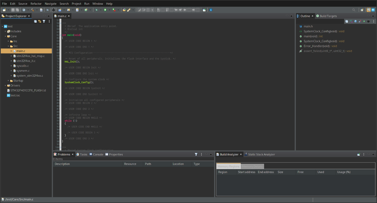
These options have been neatly laid out for you in this graphical interface! The resulting generated code files provide commented blocks within which to write your own user code, which can be seen in the main.c file visible in the previous image.
Last but not least, by switching to STM32 and using the STM32CubeIDE, a powerful live debugging interface becomes available, something that Arduino lacks.
Live debugging allows you to step through your code line-by-line while it is running. You can place breakpoints to pause your program at certain lines for inspection, and even view live, constantly updating variables without needing to write a single print statement or any other code.
Simply press the debugging button when ready to test a program, and the code will automatically compile, upload, and pause at the start of execution.
Live debugging drastically increases productivity when writing and testing code, particularly for embedded systems.
Migration – Hardware
Another necessary step in the transition from Arduino to STM32 is understanding and addressing the key hardware differences between the two families.
Perhaps most critically, especially if your embedded device is built into a custom PCB, is that STM32 chips use a logic level of 3.3V, as opposed to the 5V level encountered with Arduino.
While 3.3V is more “standard,” and will also be compatible with something like a Raspberry Pi, it can still be a jarring transition to make after spending so much time working at 5V levels used by Arduino.
This means that in any supporting circuits, PCBs, etc. that you have integrated Arduino microcontrollers into, it is necessary to now ensure a 3.3V supply is available and that this is what is powering your microcontroller.
Additionally, make sure that any inputs, such as GPIO pins reading the status of a switch, or analog pins reading a variable resistor, are limited between 0 and 3.3V. Driving a GPIO pin with 5V will usually destroy the chip!
If working with communication protocols like SPI or I2C, either adjust the slave device (i.e., a sensor) to a 3.3V version, or use a logic level converter between the microcontroller and the device.
If you are mounting your microcontroller on a custom PCB, then it is also necessary to adjust the surrounding circuitry compared to what may have been done for an Arduino chip. Exact values and practice can vary slightly from chip to chip, but it is generally advised to place a ceramic bypass capacitor at each power supply input on the microcontroller.
Additionally, a mandatory external capacitor or two, generally called VCAP, is also required.
To take full advantage of the more capable hardware, you may also wish to provide the STM32 chip with an external clock oscillator and a dedicated voltage reference IC for the analog reference pin (this makes the ADC reference point extremely stable compared to just connecting it to the same supply used for power).
You may have done one or all of these things before with Arduino chips, but they should be considered doubly important now. There’s no use making a change to a powerful chip if it falls short of its full potential because of a noisy power supply or analog reference.
Finally, the interface for uploading code to the microcontroller is different. If you are used to just Arduino development boards, then most likely you have only uploaded code directly over the USB port on those boards.
For those who have created their own PCBs with Arduino-compatible microcontrollers onboard, it is likely that you are also familiar with the AVR-ISP programmer, which connects to an SPI interface as well as the reset pin on the microcontroller.
This would have taken the form of a 6-pin breakout on the PCB, which is also present on most Arduino dev boards using AVR chips. Out of the box, an STM32 chip can use neither of these interfaces to upload code, and instead uses the default programming interface for ARM microcontrollers, JTAG/SWD.
The pinout for this interface can be found online and may take the form of either a small 10-pin interface or a larger 20-pin interface.
In either case, you will also need to obtain a compatible debug probe, which will have a ribbon cable on one end for connecting to your JTAG/SWD interface and a USB port on the other end for connecting to a computer.
Note that this generally also applies to dev boards. If you are able to upload code to an STM32 development board directly over USB, you probably have a Discovery board, which are development boards made by ST that include a built-in programming chip.
When it comes to choosing a debug probe, the most straightforward option is to use ST’s own debug probe designed especially for STM32 chips, the ST-Link. This will have guaranteed compatibility with all of the STM32Cube software covered in the previous section, and will generally be plug-and-play out of the box.
More advanced users may want to turn instead to the SEGGER J-Link series of debuggers, which are compatible with a much wider range of microcontrollers than just STM32 chips.
They boast more powerful debugging features (like unlimited breakpoints in debugged programs) combined with excellent companion software. These debug probes are also officially compatible with STM32CubeIDE with a couple changes in the settings.
Final Remarks
There are a multitude of differences and intricacies that go into the differences between developing an embedded software based on an Arduino board vs. an STM32, and many more articles could be written on the subject.
I hope that this article has provided a high-level overview that will guide your transition and make the jump seem less daunting. If you’ve gotten to the point where you’re considering doing so for your project, chances are it’s worth it!
This article was written by Brandon Alba who is an embedded systems developer with experience building embedded systems from the ground up. Brandon has broad experience from PCB design to Real-Time Operating Systems.

I’m using another intermediate step… using Arduino, but with higher-power 32-bit ARM processors (Teensy 3.2 and higher) and VS Code for all for the Intellisense/Code-Completion benefits, and I get one-button compile and flash.
I do the same for an ESP32 project that I bolt on for BLE connection.
Both projects are multi-module and multi-library. Both are 3v3 power and IO.
I do miss integrated debugging and spend a lot of time writing Serial.printf() commands
I also will need to find a solution for OTA flash updating.
The platforms are good enough for the beta period, and probably first few hundred sold units.
I’ll want to migrate to a platform that has integrated debugging and BLE and OTA updates.
I’m considering the Nordic nRF chip for that next round.
Does the STM family offer BLE and OTA?
Thanks a lot for this very interesting article. I would just mention that many of the advantages you put on STM32 are also true for Arduino (like .h files, functions, Eclipse autocompletion).
For me, the main advantage of STM32 is the large choice of microcontrolers, to match your need, and a far higher power of calculation on some of them.
Personnaly, I hesitated a lot and remained finaly on Arduino structure (at least for the actual project), despite the lower calculation power (I use a 2 inches screen and the pixels drawing is visible), for the following reasons:
-Far, far less documention on the web (so slower learning curve and a risk to get stuck somewhere)
-An specific IDE, very complicated to understand
-far less documentation on the hardware (I am not an electronician)
-and of course the need to rewrite the general structure (even though most of the C++ code is of course reusable.
All this for a very small gain. So I prefered not to take the risk.
I don’t say that STM32 is bad, and I will maybe migrate one day, but for a first project I would ask: do YOU really need to migrate?
Thank you Pierre for your feedback! Arduino is fine for maker projects just for fun, or for building an early proof-of-concept prototype, but for most commercial applications you will need to migrate away from Arduino fairly early.
Wow – a lot of ground covered in this article. Thanks. I’ve travelled the Raspberry Pi to STM route, and should have taken the leap to bare metal earlier.
Thanks as always for the comment Paul!
Potential typo/ clarification needed: “Perhaps most critically, especially if your embedded device is built into a custom PCB, is that STM32 chips use a logic level of 3.3V, as opposed to the 5V encountered in most STM32 chips.“
Should be “…encountered in Arduino.” or similar? If not, what chips utilize a logic level of 3.3V and power input of 5V? My understanding per STM32 datasheets is allowed VDD is 1.62V-3.3V
Thanks Casey, you are correct. I had caught that error during my proofread but then somehow forgot to fix it. Yikes, thanks for pointing this out and I’ll fix it now.