
Ultimate Guide: How to Develop and Prototype a New Electronic Hardware Product in 2026
This guide is written specifically for entrepreneurs, startups, inventors, and small businesses innovating new electronic hardware products.
Although hardware is known for being hard, it’s easier than ever for entrepreneurs, startups, makers, inventors and small businesses to develop and prototype amazing new electronic products.
Although I present each step in a linear fashion, product development is never a smooth linear progression and at times you will find yourself taking two steps back for every step forward.
Don’t get too frustrated though when this happens because it’s just part of the process.
Step 1 – Simplify Your Product
You must embrace simplification in order to have a realistic shot at getting your product to market in a timely fashion and without going bankrupt.
Product complexity can be a death trap for new entrepreneurs and startups!
Most entrepreneurs, and even most engineers, don’t understand all the consequences of various product features.
The addition of what seems like a minor feature can often drastically increase your development cost and the time it takes to get to market.
For example, something as simple as the position of a button could waste thousands of dollars, if it creates the need for more expensive injection molds.
Product simplification is a process of determining the exact core features your market wants, and working with experts to understand the implications of the various features.
Step 2 – Build Proof-of-Concept (POC) Prototype
Once you’ve simplified the product concept as much as possible, now the question you must answer is whether your concept really solves the intended problem as expected.
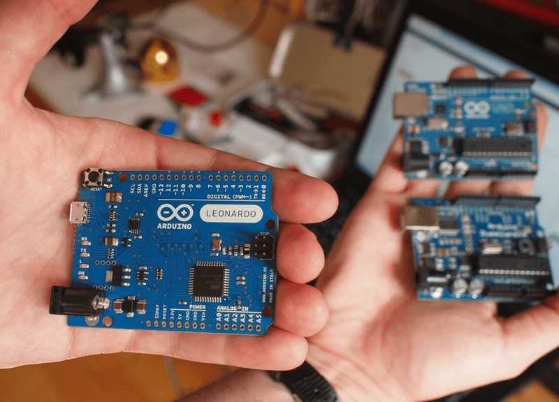
This is the goal of a Proof-of-Concept (POC) prototype which is an early prototype created using off-the-shelf components.
A POC prototype doesn’t have any custom electronics design, and is typically built using development kits such as an Arduino, ESP32, or Raspberry Pi.
Unfortunately, a POC prototype is rarely something that can be brought to market.
The production cost will usually be too high, the physical size too large, and the appearance far from ideal.
Step 3 – Create Preliminary Production Design
When developing a new electronic hardware product you should begin the custom electronics design process with a preliminary production design.
This is not to be confused with your early Proof-of-Concept (POC) prototype which in most cases can never be mass produced.
A preliminary production design focuses on your product’s production components, cost, profit margin, performance, features, development feasibility and manufacturability.
You can use a preliminary production design to estimate the costs to develop, prototype, program, certify, scale, and most importantly, manufacture the product.
Some of the questions a preliminary production design will answer include:
Is my product feasible to develop?
How much will it cost me to develop and prototype it?
How long will it take to develop it?
How much will it cost me to manufacture it, and can I sell the product at a reasonable profit?
Many entrepreneurs make the mistake of skipping the preliminary production design step, and instead jump right into designing the custom schematic circuit diagram.
By doing so, you might find that you’ve spent lots of time and hard-earned money making a product that can’t be affordably developed, manufactured, or most importantly, sold at a profit.
When creating the preliminary production design you should start by defining the system-level block diagram.
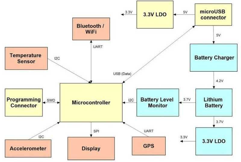
This diagram specifies each electronic function and how all of the functional components interconnect.
Most products require a microcontroller or a microprocessor with various components (displays, sensors, memory, etc.) interfacing with the microcontroller via various serial interfaces.
By creating a system block diagram you can easily identify the type and number of serial ports that will be required. This is an essential step for selecting the correct microcontroller for your product.
Hardware Academy members, here’s a great course for you to learn how to build a POC prototype and then turn it into a custom design. Not a member yet? You can join here.
Step 4 – Select Critical Production Components
Next, you must select the various production components: microchips, sensors, displays, and connectors based upon the desired functions and target retail price of your product.
This will allow you to then create a preliminary Bill of Materials (BOM).
Some of the most popular suppliers of electronic components in the U.S. include: Newark, Digikey, Arrow, Mouser, and Future.
You can purchase most electronic components in ones (for prototyping and initial testing) or up to thousands (for low-volume manufacturing).
Once you reach higher production volumes you will save money by purchasing some components directly from the manufacturer.
Step 5 – Estimate Production Cost
You should now estimate the production cost (or Cost of Goods Sold – COGS) for your product. It’s critical to know as soon as possible how much it will cost to manufacture your product.
You need to know your product’s manufacturing unit cost in order to determine the best sales price, the cost of inventory, and most importantly your potential profit.
Estimating the manufacturing cost starts with a preliminary Bill of Materials listing and pricing all of these production components.
But to get an accurate manufacturing cost estimate you also must include the cost of the PCB assembly, final product assembly, product testing, retail packaging, scrap rate, returns, logistics, duties, and warehousing.
See this article for more help estimating all of these various costs.
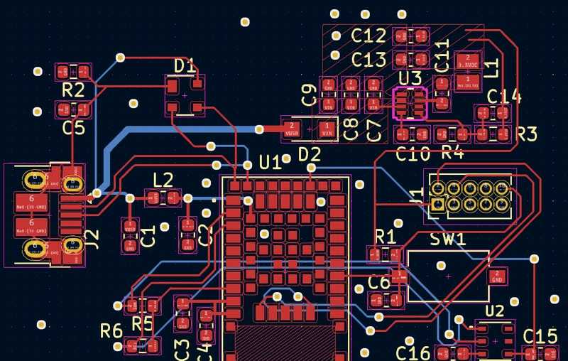
Step 6 – Design Schematic Circuit Diagram
Now it’s time to design the schematic circuit diagram based upon the system block diagram you created in step 3.
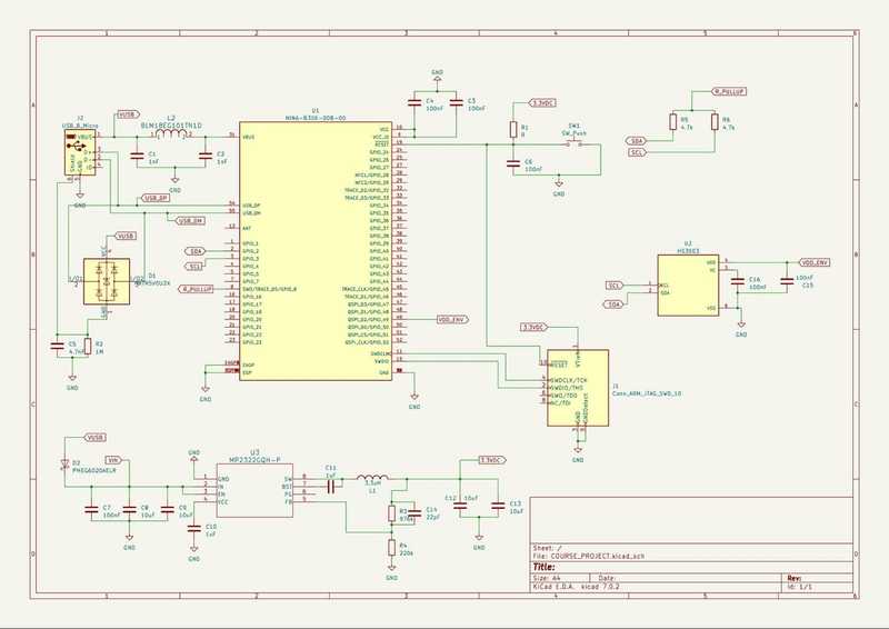
The schematic diagram shows how every component, from microchips to resistors, connects together.
Whereas a system block diagram is mostly focused on the higher level product functionality, a schematic diagram is all about the little details.
Something as simple as a mis-numbered pin on a component in a schematic can cause a complete lack of functionality.
In most cases you’ll need a separate sub-circuit for each block of your system block diagram. These various sub-circuits will be connected together to form the full schematic circuit diagram.
Special electronics design software is used to create the schematic diagram and to help ensure it is free of mistakes.
For most projects, I recommend the free, open-source PCB design tool called KiCad.
This software is very powerful and can be used for both simple and complex designs with many advanced features.
Other popular PCB software packages include Altium Designer and Eagle. But be warned these are quite expensive and are best for those designing multiple products.
DipTrace is another more reasonably priced tool, and the easiest to learn in my opinion.
What about AI circuit design tools in 2024? Although there are AI circuit design tools available so far they are too expensive and too limited to be a good option for those focused on developing their first product, or just a single product.
Hardware Academy members, here’s an introductory course for you to learn to design a PCB using KiCad, and here’s a 5-day boot camp to design your first PCB (DipTrace). Not a member yet? You can join here.
Step 7 – Design Printed Circuit Board (PCB)
Once the schematic is done you will now design the Printed Circuit Board (PCB). The PCB is the physical board that holds and connects all of the electronic components.
While developing the system block diagram and schematic circuit was mostly conceptual, a PCB design is very real world.
The PCB is designed in the same software that created the schematic diagram.
The software has various verification tools to ensure the PCB layout meets the design rules for the PCB process being used, and that the PCB matches the schematic.
In general, the smaller the product, and the tighter the components are packed together, the longer it takes to create the PCB layout.
If your product routes large amounts of power, has high-speed digital signals (crystal clocks, address/data lines, etc.), or offers wireless connectivity, then PCB layout is even more complex and time consuming.
Step 8 – Generate Final Bill of Materials (BOM)
Although you should have already created a preliminary BOM as part of the manufacturing cost estimation process discussed in step 5, it’s now time for the full production BOM.
The main difference between the two is the numerous low-cost components like resistors and capacitors.
These components usually only cost a penny or two, so I don’t list them out separately in the preliminary BOM.
But to actually manufacture the PCB you need a complete BOM with every component listed.
This BOM is usually created automatically by the schematic design software. The BOM lists the part numbers, quantities, and all component specifications.
Step 8 – Order PCB Prototypes
Creating electronic prototypes is a two-step process. The first step produces the bare, printed circuit boards.
Your circuit design software will allow you to output the PCB layout in a format called Gerber with one file for each PCB layer.
These Gerber files can be sent to a PCB shop for producing a few prototypes, but the same files can also be provided to a larger manufacturer for high volume production.
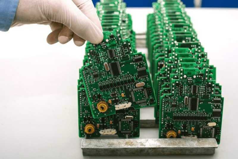
The second production step is having all of the electronic components soldered onto the empty board.
From your design software you’ll be able to output a file that shows the exact coordinates of every component placed on the board, which is commonly called a pick-and-place file.
This file allows the assembly shop to fully automate the soldering of every component on your PCB.
To place an order for custom PCB boards, whether prototypes or production, there are quite a few technical concepts and terms you need to understand first.
Any PCB manufacturer will have a lot of technical options you need to select to order any boards.
Unless you’ve ordered boards before this can be somewhat overwhelming for many the first time, even if you’ve mastered PCB design itself.
Hardware Academy members, here’s a course where I walk you through ordering custom boards from two different popular vendors. It also includes PDF guides where I define the technical terms along with my suggestions on which options to select. Not a member yet? You can join here.
Your cheapest option will be to produce your PCB prototypes in China, whether it be for your early prototypes, or for larger production runs.
Although, it can be a bit faster if you can do your prototyping closer to home, to reduce shipping delays.
But in most cases, I encourage you to prioritize minimizing your financial risk instead of paying extra to try to expedite it.
For producing your boards in China I highly recommend PCBWay, Bittele Electronics, Seeed Studio, or Gold Phoenix PCB.
All of these suppliers can produce both a few prototype boards or larger runs of thousands of boards.
In the U.S. I recommend Sunstone Circuits, Screaming Circuits, and San Francisco Circuits which I’ve used extensively to prototype my own designs.
Just keep in mind that a US supplier will usually be several times the cost of getting them from China.
It usually takes 1-2 weeks to get assembled boards, unless you pay for rush service which once again I rarely recommend.
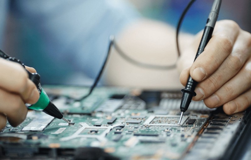
Step 9 – Evaluate, Program, Debug, and Repeat
Now it’s time to evaluate the prototype of the electronics.
Keep in mind that your first prototype will rarely work perfectly, and the first version is never ready for mass production.
You will most likely go through several iterations before you finalize the design. This is when you will identify, debug and fix any issues with your prototype.
You are only fooling yourself if you don’t allocate enough time and budget for the iterative prototyping process.
This can be a difficult stage to forecast in both terms of cost and time.
Any bugs you find are of course unexpected, so it takes time to figure out the source of the bug and how best to fix it.
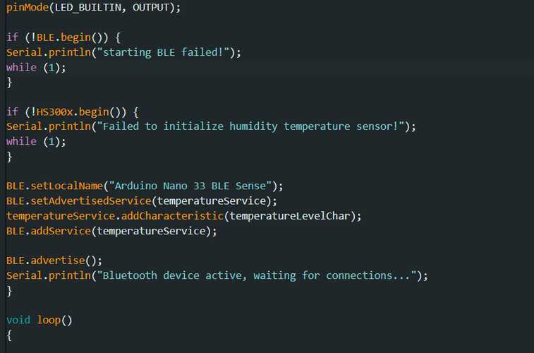
Evaluation and testing are usually done in parallel with programming the microcontroller.
Before you begin programming though you’ll want to at least do some basic testing to ensure the board doesn’t have major issues.
Nearly all modern electronic products include a microchip called a Microcontroller Unit (MCU) that acts as the “brains” for the product.
A microcontroller is very similar to a microprocessor found in a computer or smartphone.
A microprocessor excels at moving large amounts of data quickly, while a microcontroller excels at interfacing and controlling devices like switches, sensors, displays, motors, etc.
A microcontroller is pretty much a simplified microprocessor.
The microcontroller needs to be programmed to perform the desired functionality. Microcontrollers are almost always programmed in the commonly used computer language called ‘C’.
The program, called firmware, is stored in permanent but reprogrammable memory usually internal to the microcontroller chip.
For the firmware programming process you will use special development tools called an Integrated Development Environment, or just IDE for short.
One of the easiest to use, and most common IDE’s available is the Arduino IDE.
Contrary to common belief, you can also use the ArduinoIDE with a wide variety of microcontrollers. You aren’t limited to only using it with Arduino boards.
There are more powerful IDE’s available, many of which are specific to a single microcontroller family, but none are as easy to learn as the Arduino IDE.
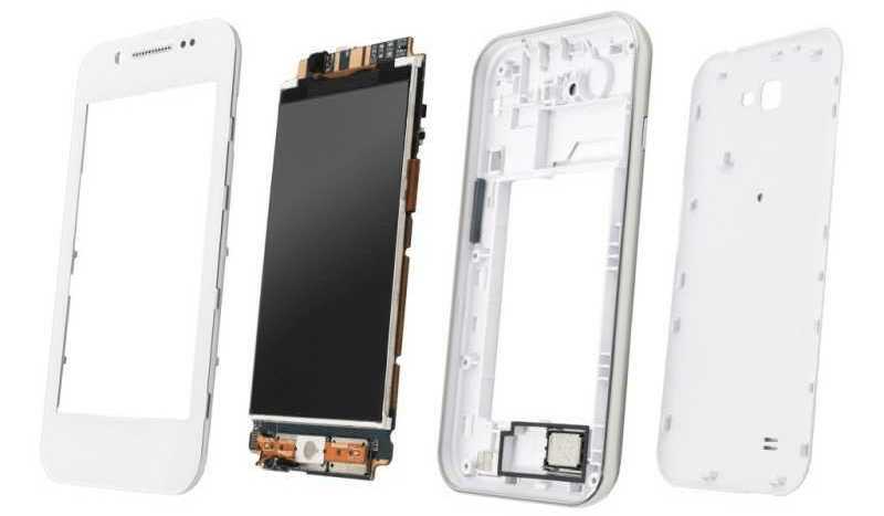
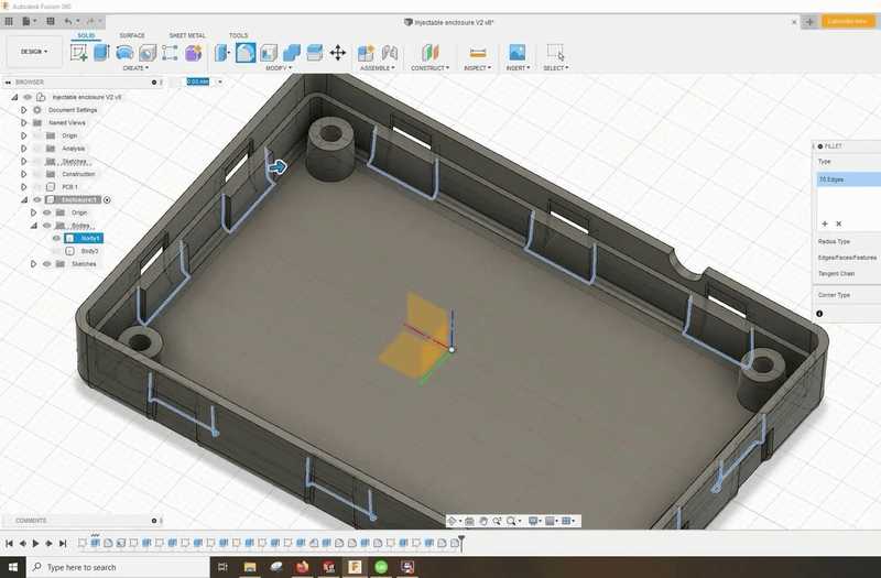
Step 10 – Develop Custom Enclosure 3D Model
Now we’ll cover the development and prototyping of any custom plastic pieces.
For most products this includes at least the enclosure that holds everything together.
Development of custom shaped plastic or metal pieces will require a mechanical engineer with experience in 3D design for injection molding.
If appearance and ergonomics are super critical for your product, then you may want to hire an industrial designer.
For example, industrial designers are the engineers who make portable devices like an iPhone look so cool and sleek.
The first step in developing your product’s enclosure is the creation of a 3D computer model.
The three big software packages used to create 3D models are Solidworks, PTC Creo (formerly called Pro/Engineer), and Autodesk’s Fusion 360.
If you want to do your own 3D modeling, and you’re not tied to either Solidworks or PTC Creo, then definitely consider Fusion 360 which is much more affordable.
Once your industrial or 3D modeling designer has completed the 3D model, you can turn it into physical prototypes using 3D printing technology most likely.
Other prototyping technologies include CNC machining and urethane casting.
You can also use the 3D model for marketing purposes, which is especially helpful when you are waiting to have functional prototypes available.
If you plan to use your 3D model for marketing purposes you’ll want to create a photo realistic version of it.
You can also produce a photo realistic, 3D animation of your product.
Keep in mind you may need to hire a separate designer that specializes in animation and making 3D models look realistic.
The biggest risk when it comes to developing the 3D model for your enclosure is that you end up with a design that can be prototyped but not manufactured in volume.
Ultimately, your enclosure will be produced by a method called high-pressure injection molding (see step 14 below for more details).
Developing a part for production using injection molding can be quite complex with many rules to follow. On the other hand, just about anything can be prototyped using 3D printing.
So be sure to only hire someone that fully understands all of the complexities and design requirements for injection molding.
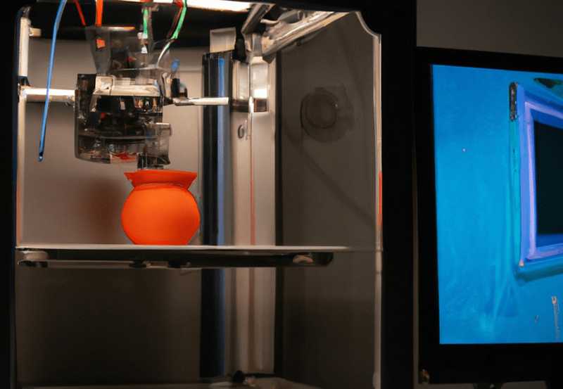
Step 11 – Produce Prototypes of the Enclosure
Plastic prototypes are built using either an additive process (most common) or a subtractive process. An additive process, like 3D printing, creates the prototype by stacking up thin lines or layers of plastic to create the final product.
Additive processes are by far the most common because of their ability to create just about anything you can imagine.
A subtractive process, like CNC machining, instead takes a block of solid production plastic and carves out the final product.
The advantage of subtractive processes is that you get to use a plastic resin that exactly matches the final production plastic you’ll use.
This is important for some products, such as those with lots of mechanical snaps or clips, however for most products this isn’t essential.
With additive processes, a special prototyping resin is used, and it may have a different feel than the production plastic.
Resins used in additive processes have improved significantly but they still don’t match the production plastics used in injection molding.
I mentioned this already, but it’s so important it deserves to be highlighted again.
Prototyping processes (additive and subtractive) are completely different from the technology used in mass manufacturing (injection molding).
You must avoid creating prototypes (especially with additive prototyping) that are impossible to manufacture.
In the beginning, you don’t necessarily need your prototype to follow all of the rules for injection molding, but you need to keep them in mind so your design can be easily transitioned to injection molding.
Numerous companies can take your 3D model and turn it into a physical prototype. Proto Labs is the U.S. company I personally recommend.
They offer both additive and subtractive prototyping, as well as low-volume injection molding.
You may also consider purchasing your own 3D printer, especially if you think you will need several iterations to get your product right.
3D printers can be purchased now for only a few hundred dollars allowing you to create as many prototype versions as desired.
The real advantage of having your own 3D printer is it allows you to iterate your prototype almost immediately, thus reducing your time to market.
Step 12 – Evaluate the Enclosure Prototypes
Now it’s time to evaluate the enclosure prototypes and change the 3D model as necessary. It will almost always take several prototype iterations to get the enclosure design just right.
Although 3D computer models allow you to visualize the enclosure, nothing compares to holding a real prototype in your hand.
There will almost certainly be functional and cosmetic changes you’ll want to make once you have your first real prototype.
So, plan on needing multiple prototype versions to get everything right.
Developing the plastic for your new product isn’t necessarily easy or cheap, especially if aesthetics is critical for your product.
However, the real complications and costs arise when you transition from the prototype stage to full production.
Step 13 – Transition to Injection Molding
Although the electronics are probably the most complex and expensive part of your product to develop, the plastic will be the most expensive to scale up.
Most plastic products sold today are made using a really old manufacturing technique called injection molding. So it’s very important for you to have an understanding of this manufacturing process.
First, you start with a steel mold, which is two pieces of steel held together using high pressure. The mold has a carved cavity in the shape of the desired product.
Then, hot molten plastic is injected into the mold to form a part in the shape of the mold cavity.
The part is allowed to cool and solidify, then it’s removed from the mold using ejector pins.
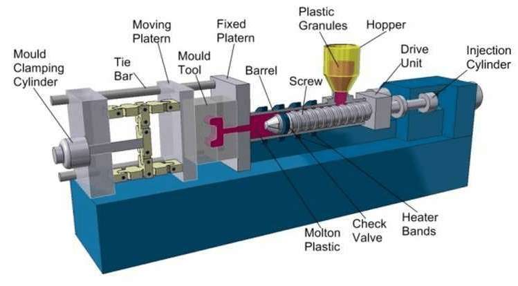
Injection molding Image supplied courtesy of Rutland Plastics
Injection molding technology has one big advantage – it’s an extremely cheap way to make millions of the same plastic pieces over and over again.
But the downside is the high setup costs due to the cost of the molds, which are shockingly expensive.
For example, a mold designed for producing millions of units can cost over $100,000, fortunately most molds are nowhere near that expensive.
The high cost is mostly because the plastic is injected at such high pressure, which is extremely tough on a mold.
To withstand these conditions molds are made using hard metals.
The more injections required, the harder the metal required, and the higher the mold cost since harder metals are more difficult to machine into the required shape.
For example, you can use aluminum molds to make several thousand units (up to about 10,000 units) because it’s a soft metal that degrades very quickly.
However, because it’s softer it’s also easier to machine into a mold, so the cost is lower. For instance, a simple aluminum mold may only cost a couple thousand dollars.
As the intended volume for the mold increases so does the required metal hardness and thus the mold cost.
The lead time to produce a mold also increases with harder metals like steel. This is just because it takes the mold maker much longer to machine a steel mold, than a softer aluminum one.
You can also eventually increase your production speed by using multiple cavity molds, which also lowers the cost per unit, but drastically increases the mold cost.
Multiple cavity molds allow you to produce multiple copies of your part with a single injection of plastic.
But don’t jump into multiple cavity molds until you have worked through any modifications to your initial molds.
It’s wise to run at least several thousand units before upgrading to multiple cavity molds.
See this article for more details on designing for injection molding.
Step 14 – Certify the Product
All electronic products that are sold must have various types of certification. The certifications required vary depending on what country the product will be sold in.
I’m going to mainly discuss the certifications required in the USA, Canada, and the European Union.
Even though these are mostly electrical certifications, you need to get the finished product certified with the enclosure, and not just the bare electronics.
This is why you need to design your product from day one with certifications in mind, but in general the actual certifications are done as late as possible, while setting up manufacturing.
If you certify too early, then any design changes will require you to recertify the product. So, it’s better to wait until the product is finalized with no more changes expected.
Certifications are a complex topic so I suggest that you consult with an expert in certifications before you go too deep into developing your product.
There are many tricks and tips that can drastically reduce your certification costs if they are implemented from the start.
Also, keep in mind that for many products, these certifications will not be necessary for doing small sales tests.
This allows you to prove the product in the market before investing in the additional cost of these certifications.
See this article for more details on all of the various certifications required for new electronic products.
Conclusion
This article has given you a basic overview of the process of developing and prototyping a new electronic hardware product.
My goal is to help you fully understand how to develop your product in a more predictable fashion with less risk.
This article was written by John Teel.
Check out our library of in-depth articles on both product development and hardware entrepreneurship.
If you prefer video, then check out my YouTube channel where I teach both hardware entrepreneurship and product development. Also see my podcast and courses.
Finally, if you want my personal help with your project, along with help from lots of other experts, then the way to get it is inside my Hardware Academy platform.

Thanks John, it helps me a lot. Good Job.
I am a practitioner in the PCBA processing industry. I like your content very much, and I also think it is very helpful to me.
Thank you very much. This article has been very helpful to me. It provides a detailed explanation of the process from circuit board to product, and thoughtfully includes related video tutorials. I will continue to learn more in the future. Thank you!
Thank you very much. This article has been very helpful to me. It provides a detailed explanation of the process from circuit board to product, and thoughtfully includes related video tutorials. I hope we have the opportunity to collaborate in the future.
KSN
I work as a foreign trade salesperson in a pbca company. Reading your content has helped me gain a lot of professional knowledge. Thank you very much.
Thanks John, it helps me a lot. Good Job. If I want to design a smart device, I need to consider the design of the wireless communication end. Could you provide some suggestions?
This is an excellent long article, but I persisted in reading it. honestly, you know more about the process of making electronic product prototypes than we do. We could cooperate someday.
Where do i see a hardware product designer/developer to hire or outsource to?
I am a practitioner in the PCBA processing industry. I like your content very much, and I also think it is very helpful to me.
I am in the process of developing a new prototype, and I think this article has saved me a lot of hustle. Thanks!
Always fantastic to hear!
Wow I wished I had read this article before starting on creating prototype. I have literally faced most of the challenges mentioned in this article.
wow, this is a very thoughtful article. I have gathered a lot of knowledge. thank you for providing us so high-quality content.
Very insightful and comprehensive overview. Liked the way it was articulated with all the necessary details to be aware of in the initial understanding. Very well written article. Such an extensive effort is highly plausible…
Thank you so much Rohit and I’m glad you found it insightful!
Thank you for your work! This website is exactly what I’m looking for.
Great articles, and it rhymes with my current initiative.
Well done, John.
Thank you, glad it was helpful!
“Lithium Battery Certifications (UL1642, IEC61233, and UN38.3)”The correct is IEC62133, not the IEC number on that title.
Oops, thanks for finding that typo, and I will fix it now.
Cheers,
John
Thank you for this nice article. Question, in case that you have already electronic boards and you need to make it one, is that possible? The board all together are 5 and not bigger than 2x5cm.
I forget to tell you that all electronic boards are already existing in the market.
Thanks for the write up.
Is it ok. to use Arduino IDE for product development not prototype.
Yes, definitely you can use Arduino IDE for development.
Very productive article and guide, love to follow more articles like these
Thank you for the comments and happy to hear my content is proving helpful. If you need further help be sure to check out the Hardware Academy where you can get not only my direct help but also help from lots of other experts.
Ok. Thanks
Thanks for the article I am an Electrical Engineer who works in the design of PCB’s and RF systems for a living. I plan on doing everything myself and the task seems daunting. I cant fathom not being an engineer with training in these areas and trying to learn all the various software, programming, and electrical engineering needed just to get a prototype that will most likely need more iterations! Not to mention the electronics equipment needed just to troubleshoot and test your hardware!
Hi Peter,
Thanks for the comment. There is definitely much to learn. Many entrepreneurs without the skills to do the development themselves have to either outsource it, find an engineer to be a co-founder, or partner with a manufacturer.
Also don’t forget that product development is just a small piece of the entire puzzle to get a product to market. The biggest mistake engineers tend to make is they over focus on the product development while neglecting even more critical steps like customer development and marketing. You must speak with customers first and you need to begin your marketing efforts as you develop the product. You’ll find a lot of articles where I discuss all of this here on this blog.
Best wishes,
John
Well… around all internet this page is the best.
Where do you recommend an entrepreneur starts when it comes to schematic design.
A full of amazing details! Thanks John
Hey john,
Is there any tool for schematic circuit design?
Hey im really new to hardware kinds of stuff, I decided to take my website to hardware type idk it’s possible or not like see I already created website, yes my future users can use the website but I want to take that into hardware so they can plug into T.V and they can surf through it without knowing that its website based type hardware, see I don’t know much about hardware so if I did mistake so sorry for that
Wish i had seen this site earlier. Wonderful article. What software do you mostly use for the system block diagram? I am new and so far developed two(2) simple products.I use KiCAD. Because of the complexities of enclosure designs, i design the PCB based on an existing enclosure. I know this approach is not feasible always though but the manufacturers are most often prepared to customize for a small top up.
Hi John,
Thank you very much for the great article!
But I’m wondering, how would you go about connecting your product to the internet and say a smartphone app?
Thank you very much!
Berend
Thank you Berend! Most likely via WiFi for the internet, or Bluetooth LE for a smartphone app.
This article is really helpful to understand the overall procedure for an electronica product development! Much appreciate for your spirit of knowledge&experience sharing!
Hi John,
Just wanted to drop a quick thank you for your content.
It’s a good read every time, and refreshingly honest.
For a startup, it’s a great sanity check to see how things usually progress and to be able to compare where we are with respect to it.
It’s also good to see where we may need help, and how.
Your honesty makes me want to reach out to you, hands down, when/if I may need your expertise: I know that you’ll tell it to me as it is, just the way I’d like it.
Thank you Talar! I’m here to help you whenever you need it.
Best wishes,
John
Hey John,
I love reading your writings. Your predictable hardware report, XLS spreadsheet, is incredible! Well worth many times the low price you charged. I am not sure if you have a sample hardware report listed for viewing by potential customers. If not, you should. It has way more information than I thought it would have! It is virtually a full road map from our concept to manufacturing with every spec and cost estimate included. (We are very pleased!)
Emerson Bone
Wow, thank you so much for that Emerson! I’m really pleased that you are finding the Predictable Hardware Report I developed for your product to be so helpful!
And thanks for sharing the praise as a public comment too:)
Let me know if you have any questions, and I’m here to help.
Best wishes!
Hi John,
Amazing article! Interesting insights to the new product development cycle. I wrote an article on the design thinking for new product development. Do take a look if you find the time.
https://www.linkedin.com/pulse/some-thoughts-prototyping-vs-product-design-vipin-venugopal/
Hi
Well… around all internet this page is the best.
Its the only one that have a really useful information about how to create a a new design.
Congrats 🙂
And Thanks.
“I initially hired a couple freelance mechanical engineers. However, I quickly became frustrated with how slow things progressed. After all, I was thinking about my product almost every waking hour!”
Sounds like you sorta handed over the project to some engineers, and then waited to hear back from them. You could have had deadlines, at least.
I hired an engineer, and we’re making incredible progress– much faster than what i could do alone. Here’s how:
– I pay them by the hour, to meet with me for 2 to 3 hours. This is a solid block of time. We work on the engineering together. I pitch my ideas and questions, they critique and offer solutions. They’re all all mine for those 2-3 hours. No distractions. We do this by phone and remote-desktop sharing. Worth every penny.
Thanks for the comment John! I most definitely did not “sorta hand over the project”. Just the opposite and I was so active I was doing most of the debug and coming up with all of fixes and all they did was make the changes to the 3D model. What strategy is best really depends on your existing skills, your ability to quickly learn new skills, and how much money you have to spend.
Thanks again,
John
That is really interesting that the prototype printed circuit board will allow you to output the layout. Something that I am thinking about getting into is the circuit board production. That kind of stuff interests me and I would love to research more of how the layout works.
Thanks.
This is very informative article. Covering issues pertaining to the entire development life-cycle.
Hi John,
This post is very informative, thank you.
I wonder if the product needs to apply for a patent, which stage of design process do you recommend to do it?
Thanks,
Min
Thank you for the comment.
I recommend delaying the full patent as long as possible. Instead start with a low-cost provisional patent which will give you one year of protection. After that one year then you can decide if it is worth getting a patent. 99% of patents never see the market, so focus more on the market than the patent. This is a topic I write about frequently so maybe scroll through some of my older posts. I have one post just about this topic titled “Should I keep my product a secret?”.
Thanks for the reply ! I will check the old post.
Hi John,
This is Vitthal from India , you have explained about the complete product development in short and covered all the related things. It encourages to the youngsters like us and motivates towards the hardware design. We have started following you. we expect more and more notes from you. Thanks
Hello John,
Great article, super helpful.
Where do you recommend an entrepreneur starts when it comes to schematic design.
I have a general idea of what my PCB needs to have (MCU, wireless/Bluetooth, motion sensors, power regulation for Lithium batteries, etc. etc.) and I have found some chips on DigiKey etc. that seem like they fit my use case but even then I have no idea where I need resistors/capacitors or how to use SPI or I2C to have sensors interact with MCU’s. The datasheets for all the components I have found fly right over my head.
What are your recommendations?
Thanks again for putting out this amazing work for free!!!!! The whole internet owes you big time!!!!
-Saurav
Hi Saurav,
Thanks for your question and for your positive feedback!
You have two options. Either you will need to learn a bunch more about electronics design or you will need to get some outside help. It will be impossible to design a commercially viable product without a solid understanding of all the details specified in the datasheets. There are a ton of websites out there for learning electronics, but it will take considerable time for a beginner to learn everything needed to design a viable product. Keep in mind in takes engineers years of education and experience to get good at circuit design so don’t expect yourself to do it quickly.
If you want to discuss this further feel free to email me directly at info@predictabledesigns.com.
Very well explained. Thanks for all the helpful content.
Dear John,
Thanks for the revised and expanded version of the article. In fact the previous version of this article was the one after reading which I started following your blog and other articles. Good one. Informative.
Regards, Sinoj
Thank you Sinoj, I appreciate that! Thanks for following.
Hello John, One additional option you might want to mention regarding enclosures is using an off the shelf enclosure and having it tooled. One such company I’ve used is Bopla Enclosures (there may be others as well). They make a wide range of enclosures that can be tooled by them per your design. The end result is an custom made enclosure without the cost of molds or tooling. If sales volume warrants it, a custom enclosure can then be made. Thank You for the helpful information. Chris
Thanks for sharing Chris! I’ll be sure to look at this option further.
Hi John,
Your article is very very good for me, i will share it to my friends, good job.
Thank you Felix!
Dear John,
Great Work! I learnt a lot from your work, I have an idea to develop low cost routers and access points for rural schools, based on Open source OS and cheap microcontrollers, how do I go about this, is there need to program the OS, how do I select the right MCU for compatability with the OS?
How do i get started with PCB design?
How to choose value of components (Example: How many resistors will requires and of what value?) How to evaluate such calculative thing?
Does any software perform simulation for that purpose?
Hi Jayendra,
Thanks for the question/comment. However, that’s too big of a question to answer in a comment. Software exists to simulate circuits, but not to help you make the basic design decisions like how many resistors are needed. You have to review the datasheet for each component.
For doing this you need some basic electronic engineering skills (no B.Tech Degree required), like have digital electronics, network analyses and synthesis, and most important mathematics.
Hi John, I am working on our first electronic product and your blog is really a great help. Thank you very much for sharing the knowledge. Initially we are just planning to make only 200 pieces, so Injection molding doesn’t look economical for enclosures. We tried with 3D printing but the quality is not very good. Is there anyway we can get enclosures developed in such low quantity?
Hi Ashok,
You may want to still consider injection molding for 200 pieces. That is the only way you will ever get truly production-quality enclosures. You can purchase aluminum molds for about $1,500 each. You could also look at rubber molds, but I don’t have any experience with them.
Best wishes!
Thanks John! I will do a search about the rubber molds if they can suit to our needs.
you can alternatively try to use a SLA resin printer you will get the quality of a injection mold at low cost check the new Elegoo Saturn resin printer
If you need CE Marking Certification for Your Product you can feel free to contact us
I was wondering how long the CE mark process normally takes for hardware?
Thank you!
Please correct two errors in your article:
1.) UL certification is not required for any product. It’s a very good idea, but not required. Google it.
2.) It is not even necessary to use UL. They are the most-recognized Nationally Recognized Testing Laboratory (NRTL), but they are far from the only game in town. There are cheaper options that are almost as well recognized by the public and whom can perform the same function as UL, often cheaper. Companies such as MET and NSF have marks that people recognize and I have heard they are about half the cost.
I decided to skip NRTL testing on the first few orders of my product, and save up enough through orders to pay for it later. It is perfectly legal to do so, but I risk greater damages if there is a lawsuit, and certain large buyers (such as schools) would pass me up because they demand NRTL certification when buying. I took a lot of precautions in the design and I’m not targeting large buyers initially, so it is a risk I am willing to take. I think my increased focus on safety would be taken into account in a lawsuit anyway. The power adapter I chose is an off the shelf product and is UL certified, and since that is the point most likely to cause a fire I am comfortable with my choices. But you can bet that NRTL certification will happen quickly. I’ll probably go with MET. Don’t want a lawsuit squishing my new business.
Hi Christopher,
Thanks for your helpful comment. You are correct there is no government law that requires UL testing for any product. That being said because of liability risk I’ve always considered it as something that you must have if your product connects into an AC outlet. So saying it is required is technically not correct, although highly, highly recommended. I’ll definitely look further into the MET and NSF options as a lower cost alternative to UL.
Thanks again,
John
This is a treasure of a information that i needed. Much appreciated.
Hello John,
Excellent information. Great Job!
Hi John,
I found your extremely interesting as an electrical engineer with many years of experience in manufacturing custom-built products of low technology, I have joined hands with highly qualified electronics and automation product developers and also mechanical tooling specialists to develop new products . Your article gave inputs on various aspects of a product development venture, Good article, keep posting more of such stuff
Hey Papoo,
Thank you so much for the positive comment! Let me know if I can ever be of help. I do now offer low-cost consulting plans if you ever need another engineer to help out.
Best wishes,
John
i am a beginner and am stuck with what connectors do i use for final design of my project. Project is designed for 3d printer and we are mostly using stepper motors , drivers, sensors and switches.