
Home Automation with an Arduino: A Basic Tutorial
In this tutorial you will discover how to build a simple home automation solution using an Arduino microcontroller development kit and a Bluetooth module so you can control it from your smartphone.

From controlling the room lights with your smartphone to scheduling events to occur automatically, home automation has taken convenience to a whole new level.
Instead of using mechanical switches, you can now conveniently control all the devices in your home from your fingertips.
This tutorial will show you how to setup a simple home automation solution allowing you to control almost any electrical device from your smartphone.
The core hardware is rather simple and only consists of an Arduino microcontroller kit, a Bluetooth wireless module, and a relay.
Here’s what you’ll need to get started:
– Arduino UNO (or Mega, Pro, Mini – but in this tutorial we use the UNO)
– Relay module
– HC 05 Wireless Bluetooth Module
– Lamp
– 2.2k ohm resistor
– 1k ohm resistor
– Breadboard
– Jumper wires
Circuit Diagram
Once you have all the required components, here’s how you need to wire things up:

(Click here to view high resolution image)
How to Connect the Bluetooth HC-05 to the Arduino
1) Connect the Arduino’s +5V and GND pins to the bus strips on the breadboard, as shown in the above circuit diagram.
2) Power the HC-05 module by connecting the 5V and GND pins to the bus strips on the breadboard.
The HC-05 is powered using 5VDC but includes an on-board voltage regulator that generates a 3.3V supply to power the transceiver. This means the TXD/RXD pins operate at only 3.3V.
3) Connect the TXD pin on the HC-05 module with the RXD pin (Pin 0) on the Arduino. This connection allows the HC-05 to send data to the Arduino.
The reason why we pair up TXD on the Bluetooth module with RXD on the Arduino is because the TXD pin is used to transmit data from the Bluetooth transceiver, while the RXD pin is used to receive data on the Arduino.
Although the Arduino is using 5V signal levels, and the HC-05 is using only 3.3V signal levels, no level shifting is required on this particular signal.
This is because the Arduino is based on an ATmega328 microcontroller which defines a logic high as any level above 3V. So no level shifting is necessary when going from 3.3V to 5V.
However, that isn’t always true when going the other direction from 5V to 3,3V as we’ll discuss in the next step.
4) Now we need to connect the TXD pin on the Arduino to the RXD pin on the HC-05.
This connection will form the second half of the two-way communication and is how the Arduino sends information to the HC-05.
Since the receiver data lines on the HC-05 are only 3.3V tolerant, we need to convert the 5V transmit signal coming from the Arduino into a 3.3V signal.
While this is usually best done using a logic level converter, we’re instead just using a simple voltage divider to convert the 5V signal into a 3.3V signal.
As shown in the circuit diagram, we’ve connected a 1k ohm and a 2.2k ohm resistor across the GND and TXD pins on the Arduino.
This is called a resistor divider because it divides down the input voltage. We obtain the 3.3V level signal from the intersection of these two resistors.
The equation for a divided down voltage is Vout = [2.2k/(2.2k + 1k)]*5V = (2.2k/3.2k)*5V = 3.46V, which is close enough to 3.3V to prevent any damage to the HC-05.
This crude solution should never be used with a high-speed signal because the resistors form a low-pass RC filter with any parasitic capacitance on the connection.
Once you have connected the HC-05 module to the Arduino, you can power the Arduino with a 12V DC supply or USB cable.
If the red and blue LEDs on the HC-05 are blinking, then you have successfully connected the Bluetooth module with the Arduino.
We don’t use the STATE and EN pins on the HC-05 module, since they are not required for this setup.
Setting up the Relay Circuit
The next step is to connect the Arduino to a relay module, so that we can turn the connected device ON/OFF.
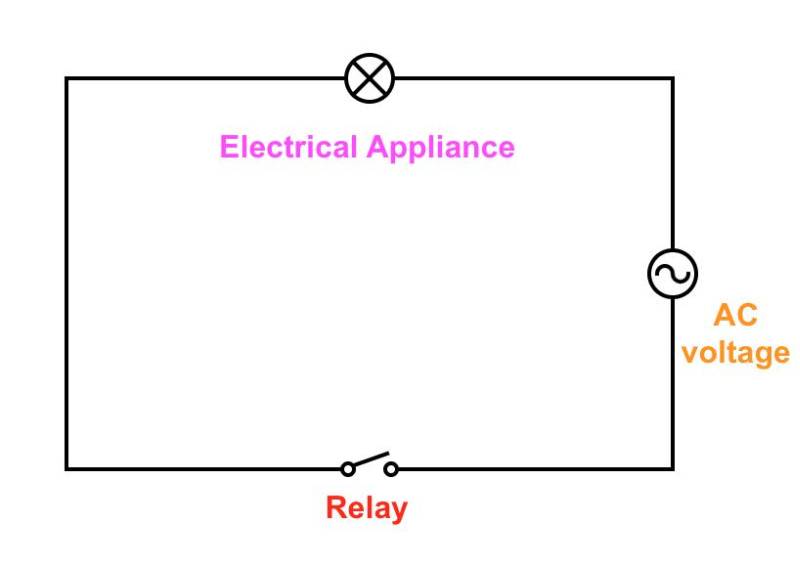
As shown in the circuit diagram above, we’ll be connecting the relay module in series with our electrical load, so that we can break the connection when we want to turn the device off and complete the circuit when we want to turn it on.
For this application we’re using a relay module which includes the relay drive circuit allowing it to connect directly to a microcontroller GPIO pin.
The relay module we’re using can handle up to 10 amps of current at up to 240V AC.
That’s enough current for a lot of devices but not enough for high power appliances like a heater or dryer. For high power appliances you’ll likely need about twice the current capacity (~ 20 amps).
You can either upgrade to a higher current relay, or place multiple relays in parallel. Two 10 amp relays in parallel are equivalent to a single 20 amp relay since half of the current goes through each relay.
DANGER: High-voltage AC can be potentially very dangerous so be sure to follow appropriate safety precautions. Predictable Designs assumes no responsibility for any injury or damage that may occur by following this tutorial.
How to connect the relay module to the Arduino:
1) First, connect the 5V and GND pins of the relay module to the bus terminals on the breadboard.
2) Next, connect the IN1 pin on the relay module with PIN 4 on the Arduino.
If you have a multi-channel module (2, 4 or 8 channels), you can connect IN2, IN3 … In(n) with different digital pins on the Arduino, and repeat the steps below for configuring the other pins.
3) Now we need to connect the AC load to the relay module. If you look carefully at the terminal block on the relay module, you’ll find these three terminals:
C: Common
NC: Normally Closed
NO: Normally Open
Here’s how the relay module works:
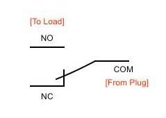
When the relay is off, the COM terminal is connected to the NC (Normally Closed) terminal, which means if you connect the bulb to the NC terminal, it will turn ON even when the relay isn’t energized.
But that’s not what we want. We want to turn on the bulb only when we send a signal from smartphone.
That’s the reason we connect the load to the NO (Normally Open) terminal, so that when the relay is triggered from the Arduino, the contact switches from the NC terminal to the NO terminal, thereby completing the circuit.
Uploading the Code
After you have successfully wired things up, the next step is to upload the code to the Arduino.
In order to upload the code, connect the Arduino through the USB port on your computer and open the Arduino IDE. After that, copy the below sketch in a new window, and try to run it on your Arduino.
#define RELAY_OFF 1
#define RELAY_1 4
char data = 0;
void setup() {
// Set pin as output.
pinMode(RELAY_1, OUTPUT);
// Initialize relay one as off so that on reset it would be off by default
digitalWrite(RELAY_1, RELAY_OFF);
Serial.begin(9600);
Serial.print(“Type: 1 to turn on bulb. 0 to turn it off!”);
}
void loop() {
if (Serial.available() > 0) {
data = Serial.read(); //Read the incoming data and store it into variable data
Serial.print(data); //Print Value inside data in Serial monitor
Serial.print(“\n”); //New line
if(data == ‘1’){
digitalWrite(RELAY_1, RELAY_ON);
Serial.println(“Bulb is now turned ON.”);
}
else if(data == ‘0’){
digitalWrite(RELAY_1, RELAY_OFF);
Serial.println(“Bulb is now turned OFF.”);
}
}
}
The code is actually pretty simple.
It initializes the relay first in the setup() method, and then waits for input on the serial port in the loop() method. If ‘1’ is received as input, it turns on the relay, and if ‘0’ is received, it turns off the relay.
Since the Arduino UNO uses its UART port for programming, it can’t communicate with the computer and receive data from the HC-05 Bluetooth module at the same time. If you have attempted the above code on an UNO, you should get the error:
An error occurred while uploading the sketch
Don’t worry though. Simply unplug the jumper wire connected to Pin 0 on the Arduino UNO (RXD pin), and re-attempt the code update.
You should now be able to update the code successfully. After programming is complete then reconnect the jumper wire.
Controlling the bulb from your Android device
Now that we have setup the hardware and successfully uploaded the code, the next step is to control the setup from a smartphone.
In order to that, you’ll need to download the Arduino Bluetooth Controller app on your Android device.
Here’s how to configure your Android device to send commands to the Arduino:
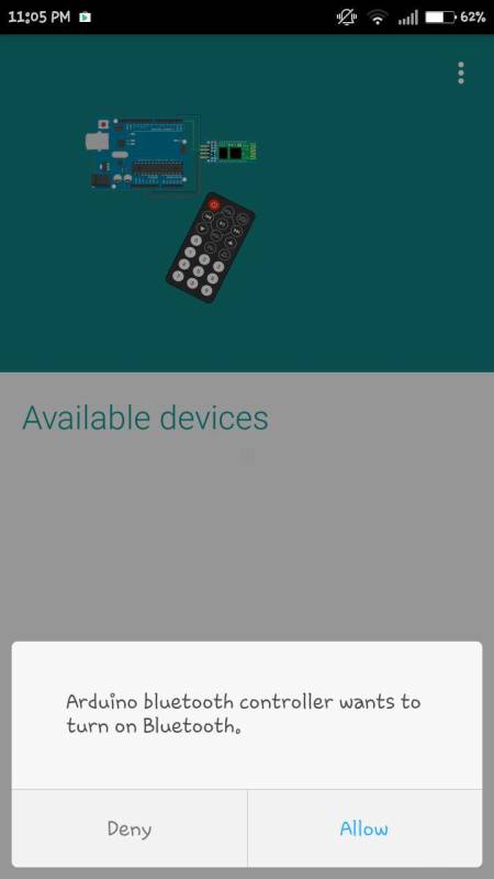
1) Open the app on your smartphone. It will ask for Bluetooth permissions. Click ‘Allow’.
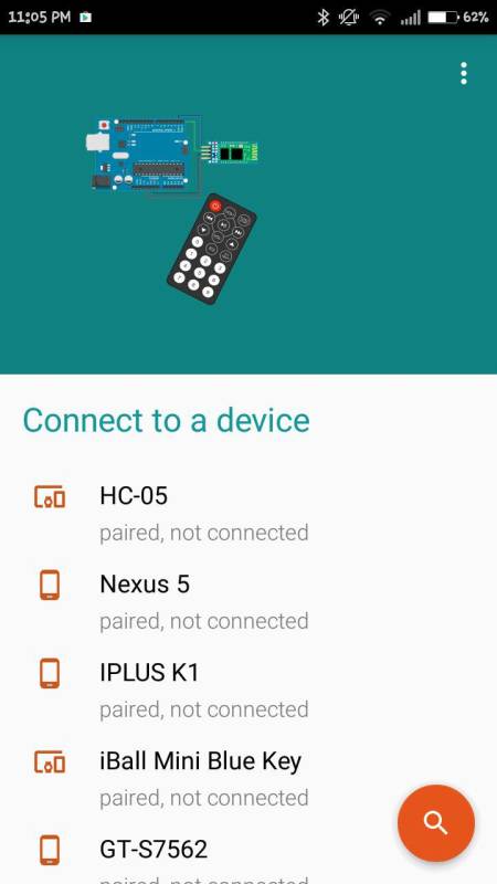
2) Next, it will list all the available devices in your vicinity. Select HC-05.
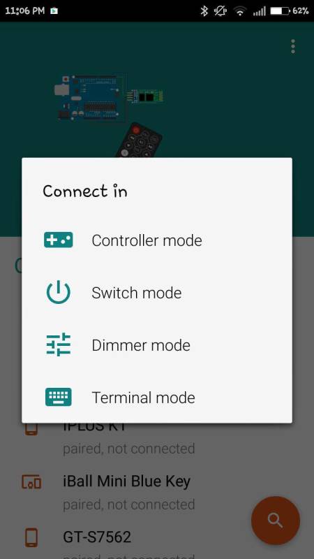
3) Once you select the device, you’ll be connected to the HC-05 transceiver. The app will now prompt you to enter the mode that you wish to use. Select ”Switch” mode.
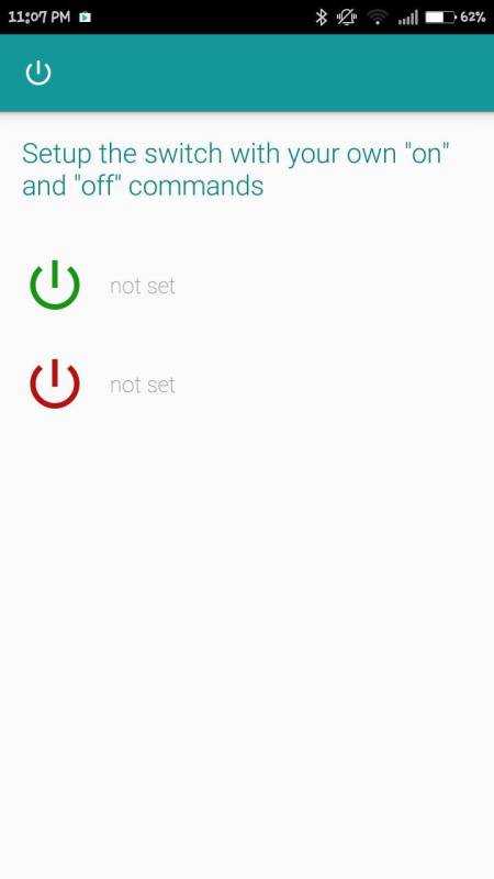
4) You should be redirected to the following screen. Click on the “Settings” icon in the top-right corner of the screen.

5) It will now ask you to set values for ON and OFF. Enter ‘1’ in the ON textbox and ‘0’ in the OFF textbox. Click Submit.
That’s it! Here’s a short video showing the setup in action:
Using the above setup, you can turn any device into a smart device that can be controlled from your smartphone.
While we used a single relay in this example, you can easily expand your system by using a multi-channel relay module.
To keep things simple, we have used a Bluetooth app that allows you to control only a single load, but in case you wish to control more devices, you can use a use a more sophisticated Bluetooth control app or write your own custom Android app.
Other content you may like:
- How to Build a GSM Cellular Panic Alarm Using an Arduino
- The SIM800 Cellular Module and Arduino: A Powerful IoT Combo
- Introduction to the STM32 Blue Pill (STM32duino)
- From an Arduino Mega Prototype to a Custom PCB
- How to Connect an ESP32 WiFi Microcontroller to a Raspberry Pi Using IoT MQTT

I think You should swap relay on and off #define values
Great post, I think people should learn a lot from this weblog it’s rattling user genial. So much great information on here.
Hi sir ,This very useful for me. actually I need to switch on my industrial camera through my mobile phone.This same circuit I will follow that .because I installed my camera inside of the machine platform.so once machine switch on I will not go to inside the machine platform. Due to that issue I will switch on the camera through my phone or pc. kindly give me the good ideas make the circuit.
there is an error occur during the verification plz help in this matter
error is stray’\342\’ in program
here is a link for a small solid state relay package that is offered in 2,4, or 8 channels.
Low price, 5v control, opto Isolated, 2 amp output is fine for most lamps.
https://www.sainsmart.com/products/2-4-8-ch-5v-solid-state-relay
hi good day do i need to find the program of the bluetooth ? thank you