
How to Update Embedded Firmware Over-The-Air (OTA)
You will learn the process for Over the Air (OTA) updates of firmware on IoT devices without having to physically interface with the device. We’ll review a simple example using Amazon Web Services (AWS) servers.

IoT devices transmit and receive data over the internet, and currently most IoT devices connect wirelessly.
When designing your next IoT device, one very important aspect that must be taken into consideration is the process of updating the firmware of the IoT device.
We are familiar with the idea that a firmware is written once to interface with the hardware, and it is rarely changed. This was, in part, due to the idea that most devices were not designed to be connected to the internet.
However, with the current rise in IoT development and deployment of devices, the definition of firmware will need to be revisited.
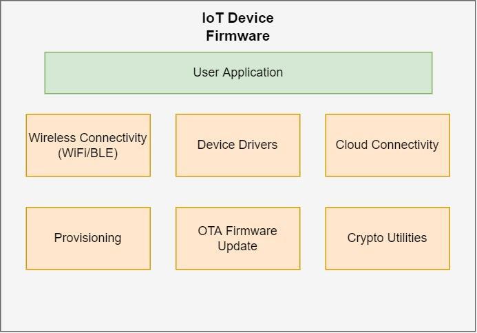
Let’s begin by exploring the different components of an IoT device’s firmware. In a typical device, you will come across the following components of the firmware:
Wireless Connectivity (WiFi/BLE) – highly dependent on the wireless connectivity protocol used. Most wireless microcontrollers come with supported protocols out of the box with easy to use APIs, such as the ESP32 microcontroller.
External Sensor Drivers – likely written by the developer of the IoT device to work with any external sensors used along with the microcontroller. If you wanted to collect the temperature in a room, for example, you would have to use a temperature sensor and write a driver to sample the data out of the sensor.
Application Specific Program – the main program of your very specific application. This is where all the different components of the firmware will be tied together to make a nice flow.
Provisioning – each IoT device will come with default settings that need to be changed to its user specific settings. For example, the configuration of an Access Point (AP) of the WiFi router with the SSID and password passed to the microcontroller to be used to connect to the internet.
OTA Firmware Update – this is one important component that should be included in your development cycle as it will enable your IoT device to be updated via the internet without having to physically interface with the device.
Cloud Connectivity – APIs and SDKs that are most likely provided by the cloud service provider to interact with the cloud. An example is connecting to an IoT MQTT broker, receiving commands, etc.
Crypto Utilities – since the microcontroller must connect to a secure cloud, the controller must be able to authenticate itself by signing and decrypting messages from the cloud. Most microcontrollers that are IoT enabled have their own libraries and support such as AES, SHA, RSA, Random Number Generator (RNG), memory encryption and decryption, etc.
These components are the fundamentals of every IoT device, although there may be more or less depending on your specific application.
In this article I will assume that you already have connectivity and the main application and sensor drivers are setup. Next, I’ll be focusing on how to add a feature that allows your device to update over the air.
OTA Firmware Upgrade Flow
Programming any microcontroller device begins with a simple C/C++ program on your host computer, and then a compiler is used to build the executable binary file (.bin).
A microcontroller specific toolchain is then used to upload the firmware binary file to the controller over USB.
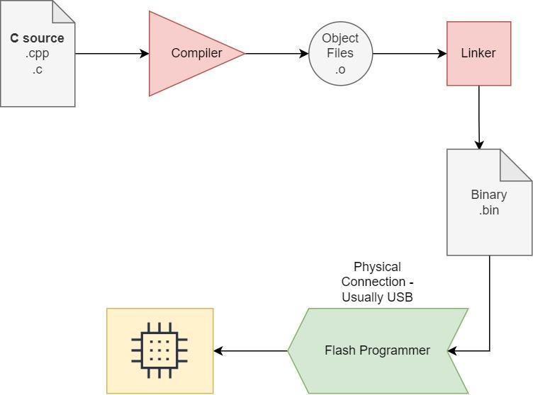
This approach is useful for debugging and developing, however it can be magnitudes harder to update the firmware binaries after the devices have been built and deployed.
This is especially true for Minimum Viable Products (MVPs) where constant improvements are needed and feedback from the user is necessary. This is why OTA firmware upgrades are an important feature that will greatly benefit the iterative development cycle.
Luckily most IoT device modules provide libraries and example code on how to conduct an OTA firmware upgrade.
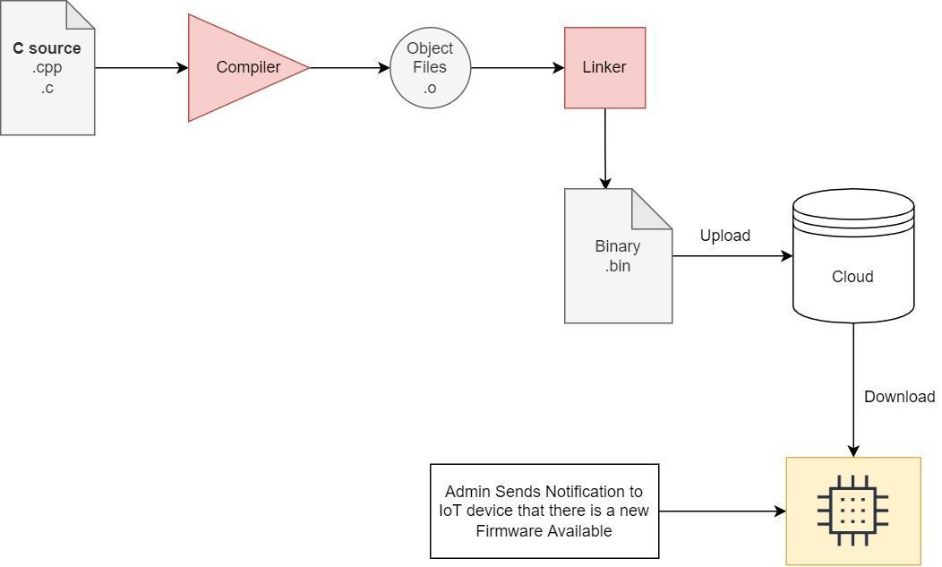
Generally, the firmware upgrade process looks something like this:
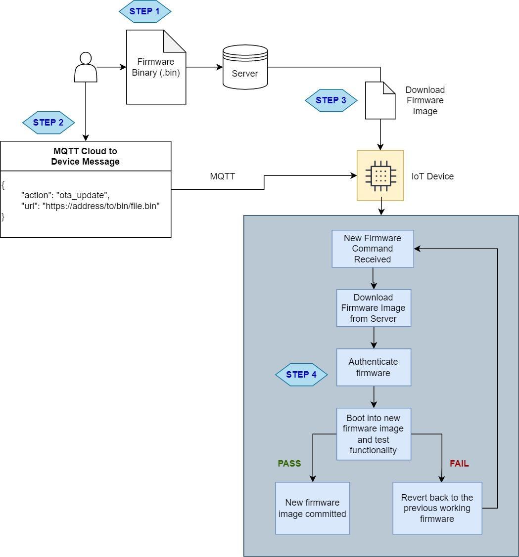
Step 1: The binary files are uploaded to a server and a URL is obtained to point to the binary file.
Step 2: A notification is sent to the IoT device that new firmware is available for download, and the URL for the firmware is provided.
Step 3: IoT device will download the firmware file using HTTP. The firmware file should be saved in a different partition (more on this shortly).
Step 4: IoT device will check the authenticity of the binary files and will start to load in the newly downloaded firmware.
A fallback mechanism should be in place after steps 3 and 4. In case the firmware file is corrupted during download, the IoT device should not load in the new firmware or free the used resources.
Let’s look at an example of using the ESP32 to demonstrate a firmware upgrade over the air.
Keep in mind that anything discussed here will apply generally to most IoT modules and should be a good starting point for developing your own IoT solution.
The OTA update should also take place outside of normal operating conditions of the device.
For example, if the IoT device is operating an important actuator that opens and closes a gas door, then the update should take place in the background while the main tasks are running and not interrupted.
This is why using a Real Time OS (RTOS) is advised, where multithreading can be used to deploy multiple tasks running independently.
OTA Data Partitions
The ESP32 allows us to partition the device’s flash to multiple partitions based on the available space.
This is very similar to computer hard drive partitions when you have two operating systems running on the same PC. For example, one partition may run Windows OS while the other may run Linux.
In an ESP32 module we have to provide a CSV file that contains the partition’s offsets and their names. Here is an example of a CSV file that outlines the partition table needed by the ESP32 to operate with OTA features:
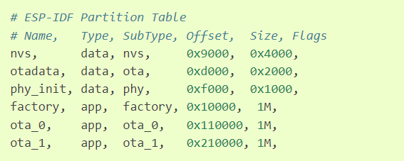
As you can see, there are three “app” types and each contains 1 MB of data size.
The “factory” app is the main firmware that will never change and cannot be updated. This is verified application code that the device will fall back to if there are any issues with either of the two OTA partitions.
The bootloader on the ESP32 will read the stored data in the “otadata” partition to see which of the three partitions is best for the app to load.
If the “otadata” partition is empty, then it will boot into the factory app partition. This is why it is necessary to make sure that the factory app contains logic to check for new firmware upgrades.
Security Measures
Attacks can occur along the process of upgrading the IoT device, thus extensive security measures should be in place for production level products.
In this sample, I won’t detail the many security features available. However, we will discuss the key elements of a secure OTA process:
- Use a secure cloud service to enable a trusted notification of a new firmware upgrade to all the deployed devices.
- The IoT device should securely download the firmware image from the cloud after connecting using HTTPS (TLS).
- IoT devices should authenticate the new firmware files to ensure that it was made by a trusted source. Using code signing techniques, once code is written and uploaded, the file will be signed.
- Then the IoT device will download and confirm the signed file if all keys match and then load in the new firmware. The device’s bootloader should also perform additional steps to ensure that the image that is being loaded into is signed appropriately just in case an injected attack happens.
Demo Steps
We will utilize the Amazon AWS S3 storage container to upload a file and perform an OTA update using an example from ESP-IDF development framework for the ESP32 microcontroller chips/modules.
Step 1: Setup an AWS account and initiate an S3 instance. There are many online instructions on how to do this step by step.
Step 2: Setup your ESP32 development environment using the latest steps provided by Espressif.
Step 3: Go to the esp-idf folder that was created in Step 2. In Windows it is usually found under C:\Users\user-name\esp\esp-idf.
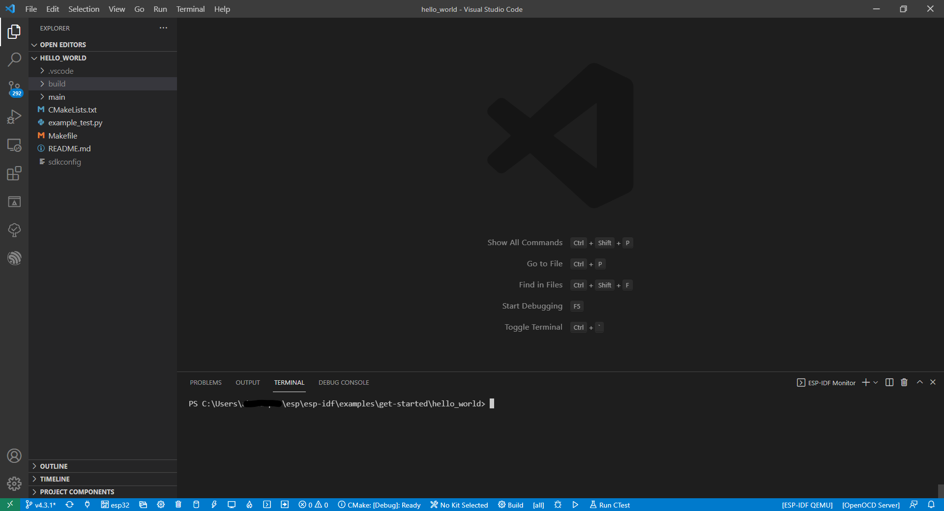
Step 4: Find the examples folder and using Visual Studio Code load the “hello_world” folder. Your VS Code should look like this:
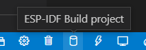
Step 5: Build the “hello_world” example code by running the following command in the open terminal “idf.py build.” Or you can also press the “build icon” at the bottom left
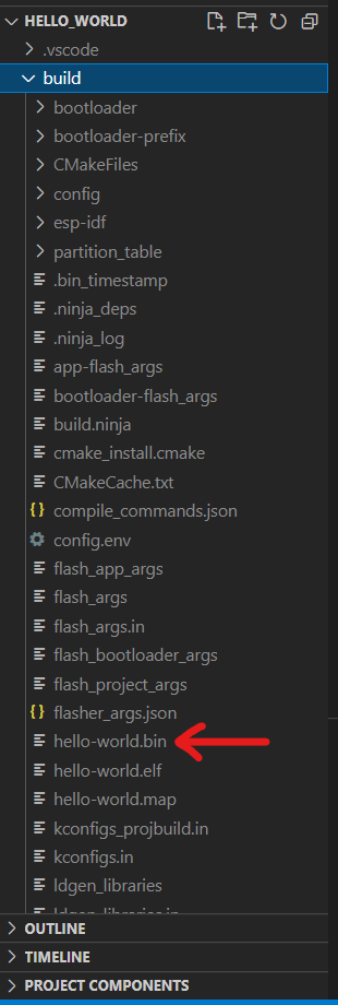
Step 6: Once the build is completed, a /build directory should have been created in the explorer to the left. Navigate to the build folder and find the “hello_world.bin” file.
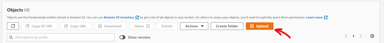
Step 7: Head over to your newly created bucket on AWS S3 and press on Upload to upload the “hello-world.bin” binary file.
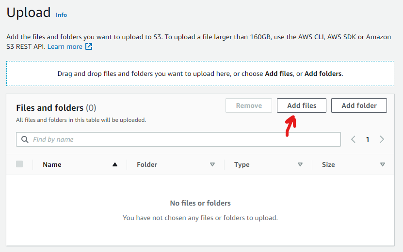
Step 8: Press on Add files on the next screen.
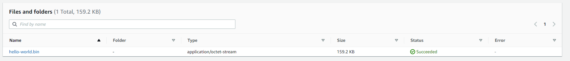
Step 9: Find and upload the “hello-world.bin” binary file in the /build directory we saw in the previous steps.
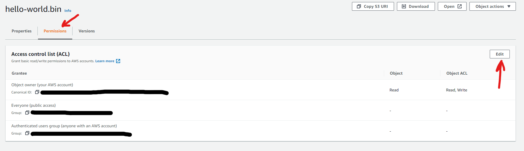
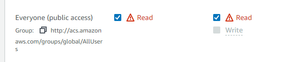
Step 10: Click on the “hello-world.bin” file that just uploaded in the bucket to change permissions to allow access to the public only for this specific file.
This is not recommended for production, where you will want to use signed links or other security methods.
Step 11: Click on the Permissions tab and then Edit.
Step 12: Set to allow public read permissions.
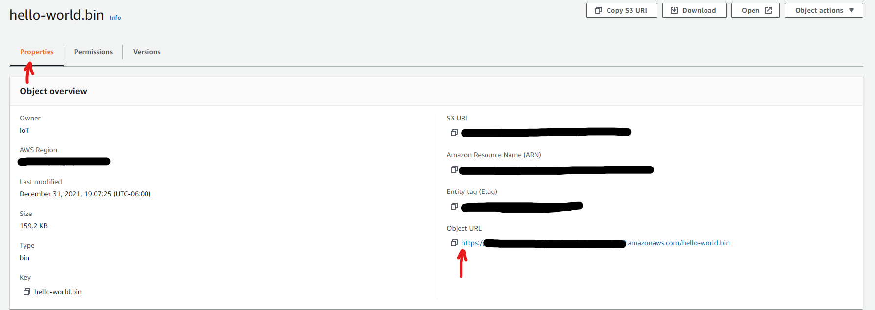
Step 13: Now go back into the Properties tab and copy the Object URL.
Step 14: Open a new window in Visual Studio Code and open the “simple_ota_example” directory under the ESP-IDF root directory.
The full directory should look something like this:
/esp/esp-idf/examples/system/ota/simple_ota_example
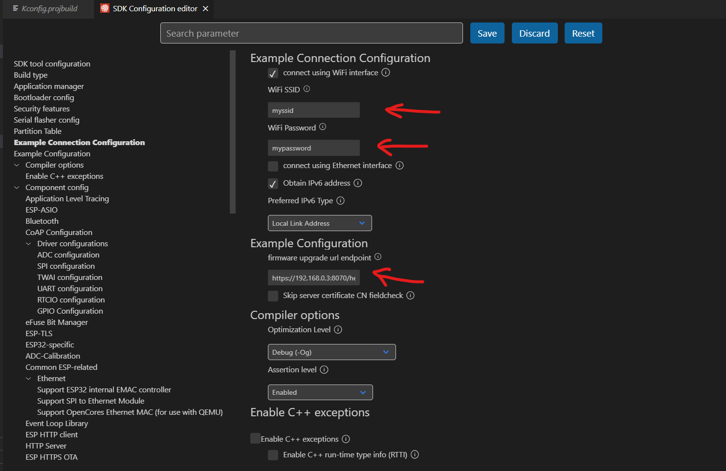
Step 15: Click on the SDK configuration in the bottom left of the Visual Studio Code screen.

Step 16: In the SDK Configuration Tab, go to the Example Connection Configuration and Example Configuration sections and change the WiFi SSID and password for the WiFi router.
Then paste the link we obtained from Step 13 into the firmware upgrade URL endpoint.
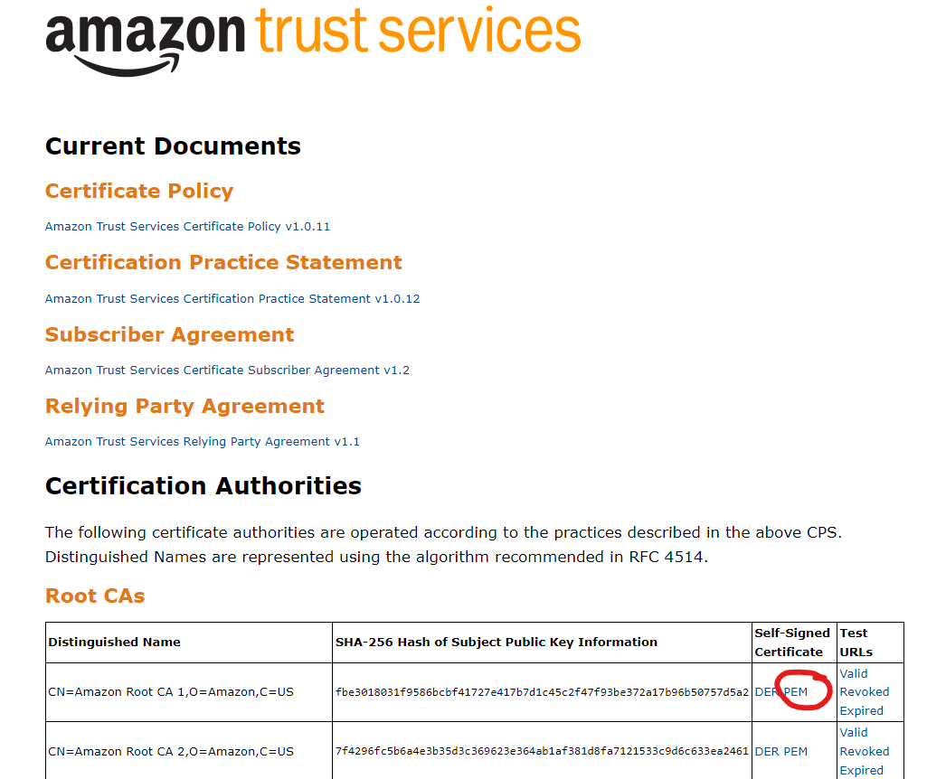
Step 17: Replace the server root CA certificate in the “server_certs” directory with the AWS root certificate by downloading it here. Be sure to download the PEM file format and replace the “ca_cert.pem” file.
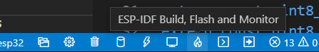
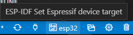
Step 18: Click on “Build, Flash and Monitor” at the bottom left to begin flashing the firmware and monitor the serial monitor. Make sure that you selected the correct COM port number, and the correct target device as “esp32”.
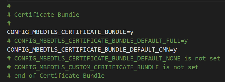
If you get a FAILED due to the x509_cert_bundle, then do the following:
- Go to the sdkconfig.
- Comment out “CONFIG_MBEDTLS_CERTIFICATE_BUNDLE_DEFAULT_FULL”
- Uncomment “CONFIG_MBEDTLS_CERTIFICATE_BUNDLE_DEFAULT_CMN”
- Add a “=y” at the end.
- Save and rerun the “Build, Flash, Monitor” command.
Step 19: If all goes well, you should see in your ESP32 serial monitor that it is currently downloading and saving as the new firmware.
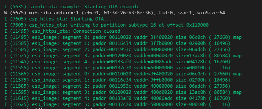
The ESP32 should restart and the “hello_world” firmware image should be the running version and can be seen from the serial monitor. Thus a successful OTA update has been completed.
This is generally the approach and process for any OTA feature on an IoT device. The following items need to be taken into account to improve the base example that we discussed in this article.
- Connect the device to AWS IoT Core using MQTT protocol to upload sensor data and other environmental data. This will keep a secure connection between the device and the AWS servers.
- Use AWS IoT Core Jobs to notify the device that it has a new firmware image that it needs to download.
- Implement code signing techniques to ensure that each new firmware image is verified by the IoT device, thus your IoT module/device should have a way to calculate and obtain keys from signatures.
- Factory app should maintain its own partition in the flash memory of the embedded system. This will ensure that if anything happens to the OTA firmware image there is a fallback available.
This article was written by Ahmed Al Bayati, who has been designing and deploying Internet of Things (IoT) devices for the past 4 years. The IoT devices he designs range from consumer products to industrial level products. Ahmed enjoys sharing his industry knowledge and helping others develop new IoT products.

Thanks, John. Very elaborate article.
We’ve actually applied OTA firmware update in our product similarly to this.
I’ve managed to modify successfully the partition table on our ESP32 to use the most room for data logging.
If anyone needs help with that please write
Thanks Edo! And thanks for the offer to help others!
As ever – this is a super helpful and timely article! We’re planning to do just this for our product – but take it to a further level by laying over this strategy a commercial aspect – where end users can buy additional or alternate functionality as “software updates” and OTA update their devices as they see fit. This opens up at least the hint of ongoing revenue for the business after the initial hardware sale. I’d be curious how you’d recommend this approach be interlaced with services like Apple’s App store. Or can that even be done?
Great article, very clear and easy to follow thank you!
Great to hear, thank you Tom for the feedback!
Cheers,
John