
Introduction to Rapid Hardware Development
There is an accepted method of failing when it comes to developing something new and the phrase is “fail fast.” Startup culture is synonymous with this phrase and for good reason. The fail fast method for hardware is a bit of a different story.

This article is a guest post by Craig Rettew who is an electrical engineer. He is also one of the experts available to help you inside the Hardware Academy.
Failing fast means getting answers as soon as possible by rapidly developing and testing a product and gathering feedback on what did not work so it can be iterated on quickly.
This method works well with software; press publish, reach the masses, and see what happens. The majority of the time, if there is a bug, it will not cause an airplane to fall out of the sky.
Failing Fast with Hardware
The fail fast method for hardware is a bit of a different story, although, it is much more attainable than it has been in the past. It takes a decent amount of time and effort to get to the point where you can release a piece of hardware to the wild.
The fail fast method with hardware is getting a bit easier with the advent of desktop 3D printers. If a dog is man’s best friend, a 3D printer is a hardware engineer’s second best friend.
A mechanical engineer could design something in the morning, send it to their 3D printer, eat a sandwich for lunch, and they will have a physical part in their hands on the same day. If something doesn’t fit right, they tweak the 3D model, and run the printer again. Talk about a glorious iterative process!
There is a wide variety of 3D printers and some can closely approximate the material that you will ultimately use for your product.
There are even metal 3D printers which allow for complex geometry that is impossible to achieve using conventional methods. There are also companies that are producing custom PC game controllers, exclusively using 3D printed parts.
A change to the plastic or even metal does not require any one to move mountains and modify a steel tool for injection molding or re-running the milling machine. No, it’s just a tweak to the 3D model. Call it a day.
I recently learned that there is a company 3D printing rockets. Yes, the ones that go to space. They are taking the fail fast concept to a whole new level and it is impressive to witness.
Electronics Has Entered the Conversation
Prototyping and failing fast with electronics can be a challenge. Breadboards or protoboards have been used for prototyping purposes since the 1970s and they are a fantastic way of swapping out parts, values, damaged chips, etc.
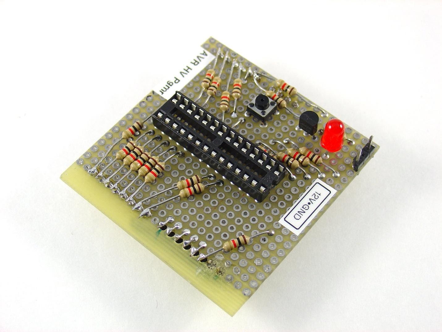
There are also Perfboards which allow for soldering parts together to be more of a “permanent” solution in lieu of manufacturing a custom PCB.
Both of these methods are still used today, however, they were introduced when surface mount technology was barely even a thing. Only ten percent of the market used surface mount components by 1986.
Fast forward to 2021 and nearly all designs use surface mount components. There is a large list of pros as to why surface mount components are superior to their through hole counterparts.
The biggest downside of using surface mount components is the difficulty to rapidly prototype with them.
Surface mount components have a huge variety of packages, although some are standardized. Passive components mostly come in standard packages such as 0805s, 0603s, 0402s, or even (get out your microscope) 0201s.
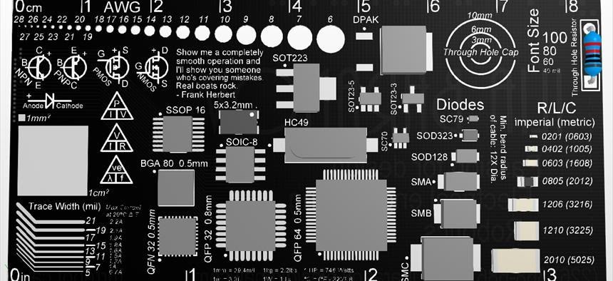
Then there are integrated circuits (IC) that have a vast number of different packages, some more difficult to use during prototyping than others. ICs also come in all shapes and sizes. You might even need to keep a microscope out to work with them.
Working with Surface Mount Components
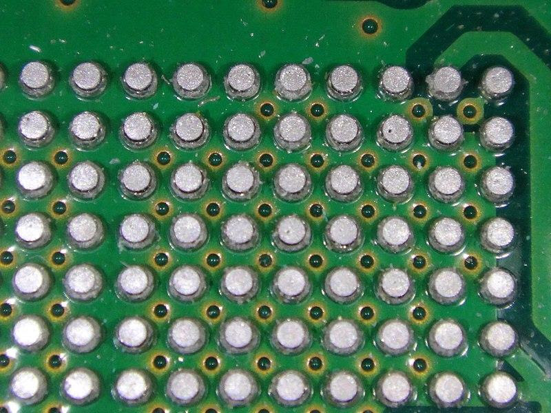
There may be a part that you would like to use in your design that only comes in a Ball-Grid Array (BGA) package which is nearly impossible to solder by hand if you do not have the right tools and expertise. These parts have all of the pins on the underside of the part, hiding from your hand-held soldering iron.
There are three different approaches you could take to prototype with a part like this:
Solder paste and a temperature controlled oven – Using this method, you would first need a PCB that has the correct pads, then you would apply your solder paste, ideally using a stencil. Finally, you would need access to an oven that can run through a certain temperature profile.
Outsourcing the soldering – This method might yield the best results but it will certainly take the most time and money. Again, you would need a PCB that has the correct pads. Then, you could send this PCB to a PCB assembly house where they will definitely charge you to solder on the part. Then you could pay for overnight shipping to get it back to you as fast as possible. I think I just heard a “cha-ching” from the shipping company.
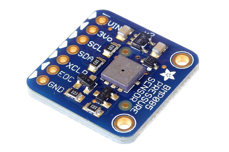
Buy a development board – This method is simpatico with the fail fast method. Almost all manufacturer’s have a pre-made development boards with the part in question. You can simply purchase this development board and it might even have the schematic and PCB files available. The manufacturer has provided the optimal design for you to toy with, a pretty sweet deal.
There can be a variety of development boards available for a given part. Most of the time, the development boards from the component manufacturer can cost $100 or more.
There are also third-party companies that make low-cost development boards along with full documentation and code.
The Development Cycle
When designing a new product, I typically peruse these third-party sites to see which development boards they offer for the type of features I need.
It is the quickest, most efficient way to test out a part to see if it will satisfy the requirements.
If you live in a country where you are spoiled with Amazon’s shipping speeds, there are cases where a development board could be ordered in the morning and at your door by the afternoon or even less. This development time is shrinking before our eyes.
Moving physical things from point A to point B takes time and that is the bottle-neck with hardware development. Still waiting on the Star Trek teleportation technology.
When drone delivery becomes ubiquitous, I implore the electronics distributors to adopt this shipping method as quickly as possible. Imagine that you got your development board but forgot that it did not include any pull-up resistors and you are fresh out.
In the not-too-distant future, you could jump on an electronics distributor’s website, order a fist full of 10kOhm resistors and have them delivered via drone in thirty minutes. Whoa, be sure to use plenty of bleach to clean up the mess from your mind being blown.

While we patiently wait for the technology to catch up with our needs, using development boards is a great way to rapidly prototype.
Most of these boards come with headers spaced out to be bread board friendly at 0.1” (2.54mm) spacing. Once you have your development boards in-hand, it is easy enough to solder on the header, plug them up on the breadboard, and interface them together.
Validation can go rather quickly once you have all the pieces connected. Having your proof-of-concept working as intended gives you confidence that it will translate nicely to your custom design.
If the documentation is available for each development board, you can use those as your guide for your custom PCB and just strip out the parts that you do not need.
Quick-Turn PCBs
Getting the development boards to behave the way you want is the first layer of development. After you have designed your custom schematic and PCB, you are going to want to test this design before making a bunch of them.
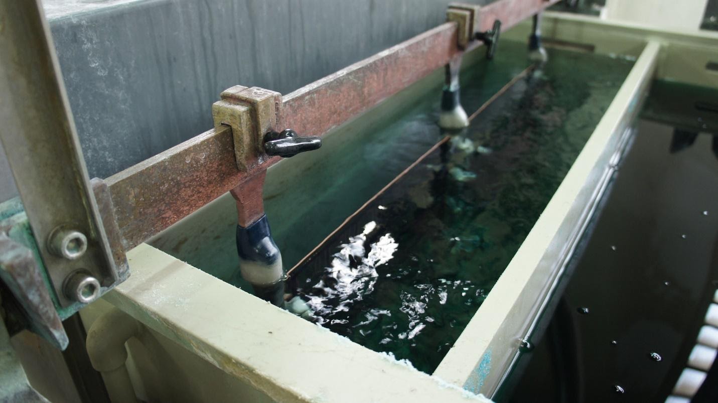
PCB manufacturing is a pretty nasty process with chemicals and such, sulfuric acid hydrogen peroxide does not sound fun to handle. It is doable in a do-it-yourself fashion but you are better off leaving it to the professionals.
There are several companies out there that offer quick-turn PCB manufacturing. You will certainly pay a premium to get a custom design fabricated and shipped to you in a couple of days but it is an option.
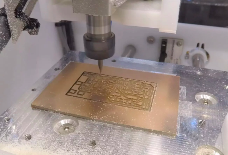
There are also desktop milling machines that can cut a basic design out of a piece of copper clad. This method is pretty limited given that there is no such thing as plated through holes. Milling a PCB could be a valid way to rapidly make your own development board.
Either way, the components will still need to be soldered on somehow which I have detailed previously.
Conclusion
There has never been a better time to develop hardware. The available tools, mountains of free education, and helpful communities allow anyone to bring their idea into existence. The barrier to entry has been lowered and the only limitation is creativity and execution.
Engineering is not all hard math and science, it is a very creative endeavor and there are endless ideas that can rapidly enter into existence. Get out your soldering iron and multi-meter and get going!

Great overview. It is worth mentioning (from mechanical engineers view) that there are also services (such as Protolabs here in the EU) that are good for quick turnaround of prototyping parts (even low volume production) such as parts having to be made in 5axis CNCs and various other technology (medical 3d printing etc).
Best regards,
Alex